Electrical Symbols Fuse Guide IEC ANSI Types and Diagrams

Electrical Symbols Fuse Guide IEC ANSI Types and Diagrams

What Is a Fuse Electrical Symbol?

When you see a fuse electrical symbol on a drawing, it simply marks a point where a fuse protects the circuit. On paper, that tiny symbol stands in for a real device whose only job is to safely melt and open the circuit when current gets too high. In an electrical schematic, panel schedule, or single‑line diagram, that fuse symbol tells you, “If something goes wrong here, this is what will blow and protect the rest.”

Basic Function of a Fuse in a Circuit

A fuse is a sacrificial safety device. Its key functions are:

  • Overcurrent protection – it opens the circuit when current exceeds its rated value.
  • Fire and equipment protection – it stops cables, PCB tracks, and devices from overheating.
  • Fault isolation – it limits how much fault current flows and where it can go.

In practice, that means the fuse is designed to be the weak, controlled link in the system: if there’s a short or overload, the fuse goes first, not the supply, busbar, or wiring.

Why One Fuse Has Multiple Electrical Symbols

Even though a fuse is simple, we end up with multiple electrical symbols for fuse because of:

  • Different standards – IEC 60617, IEEE/ANSI, national and industry standards all define their own shapes.
  • Different fuse types – cartridge fuse, HRC fuse, time‑delay fuse, fast‑acting fuse, resettable fuse, automotive blade fuse, and more.
  • Different drawing styles – detailed control schematics, PCB layouts, and high‑voltage one‑line diagrams don’t use the same level of detail.

So you’ll see a rectangular IEC fuse symbol, a classic ANSI fuse symbol, inline fuse symbols, and high‑voltage power fuse symbols—all representing the same basic function: a device that blows to protect the circuit.

Fuse vs Circuit Breaker Symbol at a Glance

You must be able to spot a fuse symbol vs circuit breaker symbol quickly:

  • Fuse symbol

    • Usually a simple shape in series with the conductor (rectangle, small box, or special curved line).
    • No moving parts are implied.
    • Often labeled with F, “FU”, or a rating like 5A, 250V, HRC.
  • Circuit breaker symbol

    • Shows a mechanical switching element (often a break in the line with a hinged or angled contact).
    • Implies you can manually reset or operate it.
    • Often labeled CB, “QF”, or with trip characteristics.

In short: fuse = melts and must be replaced, breaker = trips and can be reset. The symbols reflect that difference—one is a passive protective link, the other is an active switching device.

Official electrical symbols for fuse (by standard)

When we talk about the electrical symbol for a fuse, we

IEC fuse electrical symbols (IEC 60617)

Standard IEC fuse symbol (rectangular type)

In IEC 60617, the basic fuse symbol is clean and simple:

  • A narrow rectangle placed in series with the conductor line
  • The line enters and exits in a straight line, showing current passes straight through the fuse
  • Text like F1, F2 and the fuse rating (e.g. F1 5A) is written next to it

You’ll see this style in most modern IEC electrical schematic fuse diagrams, especially in Europe, Asia, and most international OEM products.


Alternative IEC fuse symbol with wavy line

You may also see an IEC fuse symbol with a wavy line inside the rectangle:

  • Same narrow rectangle body
  • A small wavy / zig‑zag line inside the rectangle
  • Used in many older or mixed‑standard diagrams to visually suggest a “melting element”

Functionally, it still just means “fuse” – it’s not a different device, just a different drawing style that some designers still prefer.


HRC fuse symbol in IEC diagrams

For high‑fault‑level applications, IEC uses a variation for HRC fuse symbols (high‑rupturing capacity):

  • The base rectangle fuse symbol
  • Often marked with type codes like gG, gL, aR, gR near the symbol
  • Sometimes annotated with voltage and breaking capacity, e.g. 500V 100A 50kA

You’ll see HRC fuses in industrial control panels, MCCs, and PV combiner boxes, where fault currents can be huge and the fuse has to interrupt safely.


Time‑delay / slow‑blow fuse indication (IEC)

The time‑delay fuse symbol in IEC isn’t usually a different shape; it’s marked by text:

  • Type code: T = time‑delay (slow‑blow), F = fast‑acting
  • Example: F1 T2A 250V → Fuse 1, time‑delay, 2A, 250V
  • On some IEC drawings, a note or legend will say “T = time‑lag fuse”

When you read a fuse symbol in a circuit diagram, always check the text near the symbol—shape alone rarely tells you if it’s slow‑blow, fast‑acting, or HRC.

If you’re dealing with real installations, the same notation will usually match what’s printed on the physical fuse and in the fuse panel or electrical panel drawings, similar to what you’d see in a detailed fuse electrical panel layout.

ANSI / IEEE Electrical Fuse Symbols (IEEE 315, ANSI Y32.2)

Classic ANSI / IEEE fuse symbol shape and meaning

In North American schematics, the ANSI fuse symbol is usually a small rectangle or oval drawn in series with the conductor, with short straight leads on each side. Under IEEE 315 / ANSI Y32.2, this marks a removable overcurrent protection device that is not resettable—once it blows, you replace it.

Key points of the classic ANSI/IEEE fuse symbol:

  • Single inline symbol in the circuit path
  • Simple shape (rectangle/oval) without a switching hinge

IEC vs ANSI fuse symbols comparison

When you’re dealing with electrical symbols for fuse devices, IEC and ANSI/IEEE don’t always look the same, but they usually mean the same thing functionally.

Visual differences: IEC fuse symbol vs ANSI fuse symbol

In most schematics you’ll see:

  • IEC fuse symbol (IEC 60617)

    • Usually a simple rectangle in series with the conductor
    • Sometimes a rectangle with a wavy line inside for a general / cartridge fuse
    • Extra marks may indicate HRC or time‑delay behavior
  • ANSI / IEEE fuse symbol (IEEE 315, ANSI Y32.2)

    • Often drawn as a small circle or oval with a line through it, or a narrow rectangle with pointed ends
    • Power fuses in one‑line diagrams can look more stylized, sometimes like a small “barrel” in series with the line
    • High‑voltage or dropout power fuses are drawn larger and more detailed on single‑line and protection diagrams

If you’re used to automotive or appliance diagrams, the symbol can be even more simplified. For example, many car wiring drawings show a very basic inline fuse symbol in the fuse box layout, similar to what you’d see in an [auto electrical fuse box guide

Common electrical symbols for fuse in real schematics

When you look at real‑world diagrams, you’ll see a handful of fuse symbols over and over. If you can read these, most power and control schematics instantly become easier to follow.

Generic fuse symbol you see most often

The most common electrical fuse symbol in circuit diagrams is very simple:

  • IEC style: a small rectangle in series with the wire
  • ANSI style: a thin “S”‑shaped loop or squiggle in the line

Both mean the same thing: a standard cartridge fuse that will blow when current exceeds its rating. On residential plans or older electrical fuse box layouts, this generic symbol is usually what you’re seeing.

Resettable fuse / PTC symbol

Fuse rating notation next to electrical symbols

When you see a fuse symbol on an electrical schematic, the critical details are written right beside it. If these ratings are wrong, the protection is either useless or dangerous, so I’m always strict about how they’re shown.

Voltage rating next to fuse symbol

The voltage rating tells you the maximum system voltage the fuse can safely interrupt.

Common notations you’ll see:

  • 250V, 500V, 600V, 1000Vdc, 690Vac
  • Sometimes written with phase info, like 400/230V or 480Vac

Rule of thumb: never use a fuse above its voltage rating. If

How to draw fuse electrical symbols (by hand and CAD)

Basic shape, line weight, and proportions for fuse symbols

When I draw a fuse symbol, I keep it simple and consistent so anyone reading the electrical schematic instantly knows what it is.

  • IEC fuse symbol (typical)

    • Two straight conductor lines with a small rectangle in between.
    • Rectangle length ≈ 3–4× the line thickness.
    • Line weight matches other conductor/symbol lines on the drawing (usually 0.25–0.35 mm in CAD).
    • Add tags like F1, F2 and ratings (e.g. 5A, 250V) above or below.
  • ANSI / IEEE fuse symbol (typical)

    • Two straight conductor lines with a small oval / pill shape in between.
    • Same line weight and style as IEC drawings, unless your company standard says otherwise.

Stay consistent with the rest of the drawing: same grid, same symbol height, and clear spacing so the fuse symbol doesn’t get mistaken for a connector or terminal.


Drawing fuse symbols correctly in AutoCAD Electrical

In AutoCAD Electrical, I always start from the standard libraries instead of drawing from scratch:

  • Use built‑in fuse blocks (e.g. FUSE, FUSExxx) from the Icon Menu so attributes (TAG, RATING, DESCRIPTION) are already mapped.
  • Make sure:
    • Layer matches your schematic standard (e.g. “SYMBOLS” or “SCHEM_ELEC”).
    • Snap and grid keep the fuse symbol aligned with wires.
    • Wire connection points are correctly defined so AutoCAD Electrical recognizes it as an inline component.
  • If you create a custom fuse symbol (HRC fuse, PV fuse, dropout fuse, etc.), save it into your company symbol library and keep the naming convention consistent.

For more protection components used in medium‑ and high‑voltage systems, I usually coordinate symbology with other devices like high‑voltage composite insulators so the one‑line diagrams look clean and unified.


Using fuse symbols in EPLAN and similar tools

In EPLAN, fuse symbols are handled as macro symbols with device data behind them:

  • Insert fuses via Insert → Symbol and filter by IEC / ANSI and device class (fuse, fuse‑switch, fuse‑link).
  • Use Device Tags (e.g. F1, F101) and link to the correct article/device data so ratings and part numbers follow automatically into BOMs.
  • Save your preferred layouts as window macros (e.g. fuse + fuse holder + disconnect) so designers can drop in standard protection assemblies in one click.

The same logic applies in other professional tools: keep the symbol graphic simple and let the metadata (ratings, types, part numbers) do the heavy lifting.


Fuse symbol blocks and libraries in Visio and other CAD software

In Visio, SolidWorks Electrical, and similar CAD tools, I rely heavily on reusable libraries:

  • Use stencil libraries or symbol palettes for:
    • Generic fuse
    • HRC fuse
    • Resettable fuse / PTC
    • PV string fuse
    • High‑voltage power fuse
  • Make sure each symbol has:
    • Clear name (e.g. Fuse_IEC_Rect, Fuse_ANSI_Oval, HV_Fuse).
    • Custom properties for Voltage, Current, Breaking Capacity, Type (fast‑acting, time‑delay).
  • Lock down company standard symbol sets so everyone in the team uses the same fuse symbol style across schematics, one‑line diagrams, and panel layouts.

If your projects involve current transformers, I’d keep CT symbols and product data aligned with references like the LZZBJ9‑10 current transformer so your protection schemes and fuse devices tie together correctly in the drawings.

Fuse symbol variations by industry and application

Fuse electrical symbols change a lot depending on where you work. If you jump between residential, industrial, automotive, PV, marine, or aviation, you’ll see different ways to show the same basic fuse function. Knowing these variations saves you from misreading protection devices and blowing your coordination studies.

Residential fuse symbols and panel schedules

In residential and light commercial drawings, fuses are often shown in a very simplified way:

  • On old or basic plans, a small rectangle or “F” tag can stand in for a fuse.
  • In panel schedules, you’ll see notes like “FU, 15A, 250V” to show a fused disconnect or inline fuse.
  • For retrofit work replacing fuses with breakers, drawings may mark “existing fuse” vs “new MCB”, so you know what’s actually in the field.

The goal here is clarity for installers and inspectors, not full IEC/ANSI symbol detail.

Industrial control panel and MCC fuse symbols

In industrial control panels and MCCs, fuse symbols are more standardized and detailed:

  • You’ll usually see IEC-style rectangular fuse symbols with ratings right beside them.
  • MCC buckets and feeder circuits often show HRC fuse symbols for higher fault levels, especially feeding gear like a 10kV ring main unit (RMU).
  • Control circuits use small cartridge fuse symbols or combined fuse + switch disconnector symbols for motor starters and control transformers.

Accuracy matters here because fuse type and rating directly affect fault clearing and coordination.

Automotive wiring diagrams and fuse box layouts

Automotive fuse symbols are their own world:

  • Most car manuals use a simple rectangle with “F” or the rating (e.g., 15) to mark a blade fuse in a fuse box layout.
  • In wiring diagrams, you’ll often see a rectangular fuse symbol in series with a circuit and a code like F21, 10A.
  • Inline fuse symbol: a small rectangle in series in the harness, often labeled “FUSE (INLINE)”.
  • Resettable PTC “fuses” might be drawn differently or tagged as PTC rather than a classic fuse symbol.

OEMs care more about quick troubleshooting than strict IEC/ANSI art, so expect brand‑specific variations.

Solar / PV system fuse symbols (string and combiner)

PV drawings focus heavily on DC fusing and high fault currents:

  • String fuses in combiner boxes are usually drawn as standard fuse symbols with clear DC ratings like “15A gPV, 1000V DC”.
  • Combiner boxes and DC distribution to gear such as an outdoor low‑voltage distribution box are often shown with dedicated PV fuse symbols labeled gPV or PV fuse.
  • One‑line diagrams may use high‑voltage DC fuse symbols on the DC side and standard AC fuse symbols on the inverter AC side.

Key point: the symbol may look generic, but the label (gPV, DC, voltage rating) tells you it’s a PV‑rated fuse.

Marine and aviation fuse symbols and quirks

Marine and aviation both push reliability and clear documentation, so their fuse symbols are strict but sometimes unique

Electrical fuse symbol FAQ

What is the standard electrical symbol for a fuse?

In most modern schematics, the standard fuse symbol looks like:

  • IEC (most of Europe/Asia): A small rectangle in series with the conductor.
  • ANSI/IEEE (North America): A small rectangle or oval in series, sometimes slightly tapered.

Both mean the same thing: a sacrificial overcurrent protection device that blows when current is too high.


Fuse symbol vs circuit breaker symbol

You can tell them apart quickly:

DeviceSymbol clueKey idea
FuseSimple rectangle/oval, no moving switchOne‑time protection, must be replaced
Circuit breakerSymbol includes switch contacts or a break in the lineResettable device, can be switched on/off

On one‑line or power diagrams, breakers often have more complex symbols (springs, trip units) and are labelled with frame/rating, especially for medium‑voltage and high‑voltage circuit breaker devices.


Is there a universal fuse electrical symbol?

No, there isn’t a single universal fuse symbol. You’ll mainly see:

  • IEC 60617 style (rectangle) in Europe, Asia, global OEMs.
  • ANSI/IEEE style (rectangle/oval, sometimes more stylized) in North America.

However, any small series box/oval labelled “F”, “FU”, or with a fuse rating (e.g. 5A, 250V) will almost always be a fuse in practice.


Meaning of the wavy line inside some fuse symbols

Sometimes you’ll see a rectangle with a wavy or zigzag line inside. That usually means:

  • The wavy line represents the fuse element (fusible link).
  • In some IEC drawings it can hint at time‑delay / slow‑blow characteristics (check the legend/notes on the drawing).
  • Always confirm with the parts list or legend; different companies adopt slightly different notations.

Differences between UK and USA fuse symbols

In real drawings the differences are small but important:

RegionTypical standardCommon symbol style
UKIEC / BS EN (IEC 60617)Clean rectangle with labels like F1, F2, “T2A 250V”
USAANSI/IEEERectangle or small oval, often labelled FU1, FU2, etc.

The functional meaning is the same; just watch for notation and labeling style (e.g. BS vs UL/CSA fuse codes).


Where to download CAD fuse symbols and blocks

If you’re drawing schematics or single‑line diagrams, use ready‑made libraries:

  • AutoCAD Electrical – built‑in symbol libraries; search for fuse, inline fuse, or fuse holder.
  • EPLAN, SolidWorks Electrical, Visio – all offer standard IEC/ANSI fuse symbols in their libraries.
  • Vendor libraries – many manufacturers and design platforms share DWG/DXF/STEP blocks and fuse symbol CAD packs on their websites.
  • Community sites – platforms like GrabCAD and TraceParts often host free fuse symbol CAD and blocks.

Always check that the downloaded symbol matches your standard (IEC vs ANSI) and add your own labels: voltage, current, and breaking capacity.
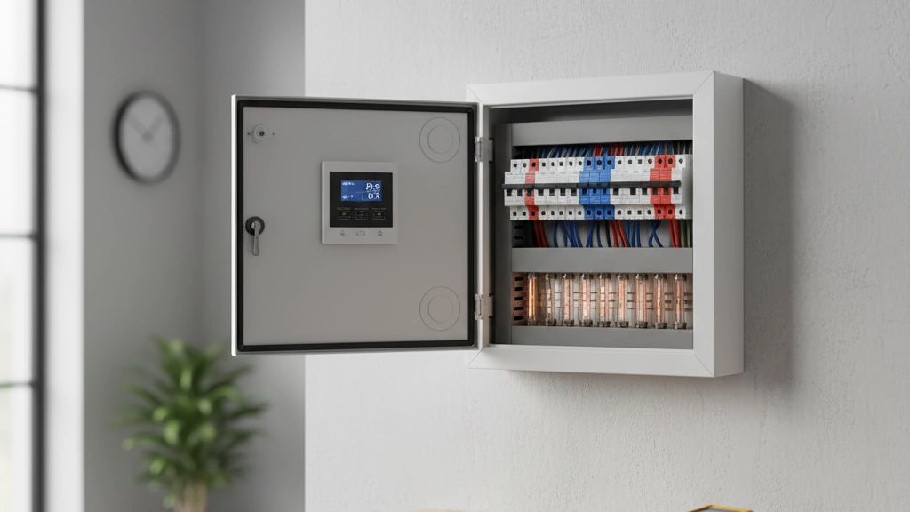
Related Posts

Low Voltage Switchgear Analysis at Key Components

Low Voltage Switchgear Analysis at Key Components

Navigating the intricate world of electrical power distribution, one quickly encounters the indispensable role of low voltage switchgear. But what exactly is ‘low voltage switchgear,’ and why should it matter to manufacturers and industrial clients alike? Simply put, it’s the electrical equipment responsible for controlling, protecting, and isolating electrical circuits at low voltage levels — […]

Read More
Medium Voltage Circuit Breaker Guide Types Specs and Selection

Medium Voltage Circuit Breaker Guide Types Specs and Selection

What Is a Medium Voltage Circuit Breaker? A medium voltage circuit breaker (MV CB) is a switching and protection device designed to safely interrupt electrical currents in the 3.6–40.5 kV range. In plain terms, it’s the safety valve of a medium voltage network: it detects faults, cuts power in milliseconds, and allows you to switch and isolate equipment without putting people […]

Read More
Switch Disconnector Guide Technical Specs Safety and Application

Switch Disconnector Guide Technical Specs Safety and Application

Core Functions & Safety Imperatives A switch disconnector is essential for safely isolating electrical circuits, providing a visible and positive break to ensure zero energy flow. This isolation meets strict LOTO (Lockout-Tagout) compliance under OSHA 1910.147 and NFPA 70E, protecting personnel during maintenance by preventing accidental re-energisation. You’ll find two main operation types: A critical safety benefit is arc flash […]

Read More