If you’ve ever stared at a wiring diagram and wondered, “Is that a fuse symbol or something else?”, you’re not alone.
Misreading a fuse symbol in electrical schematics isn’t just confusing — it can ruin equipment or, in the worst cases, start a fire. And to make things more interesting, the symbol isn’t the same everywhere: IEC, ANSI/IEEE, European, automotive, and even older legacy drawings all use slightly different marks for the same basic device.
In this guide, you’ll see exactly what each electrical fuse symbol looks like, where it’s used, and how to tell it apart from look‑alikes like circuit breakers and resistors. You’ll also learn how to read fuse ratings (like T5AL250V), and how symbols change for cartridge fuses, automotive blade fuses, HRC fuses, and resettable PTCs.
By the end, you’ll be able to pick out any fuse schematic symbol at a glance — whether you’re reading a house wiring circuit diagram, an industrial panel drawing, or a car fuse box legend.
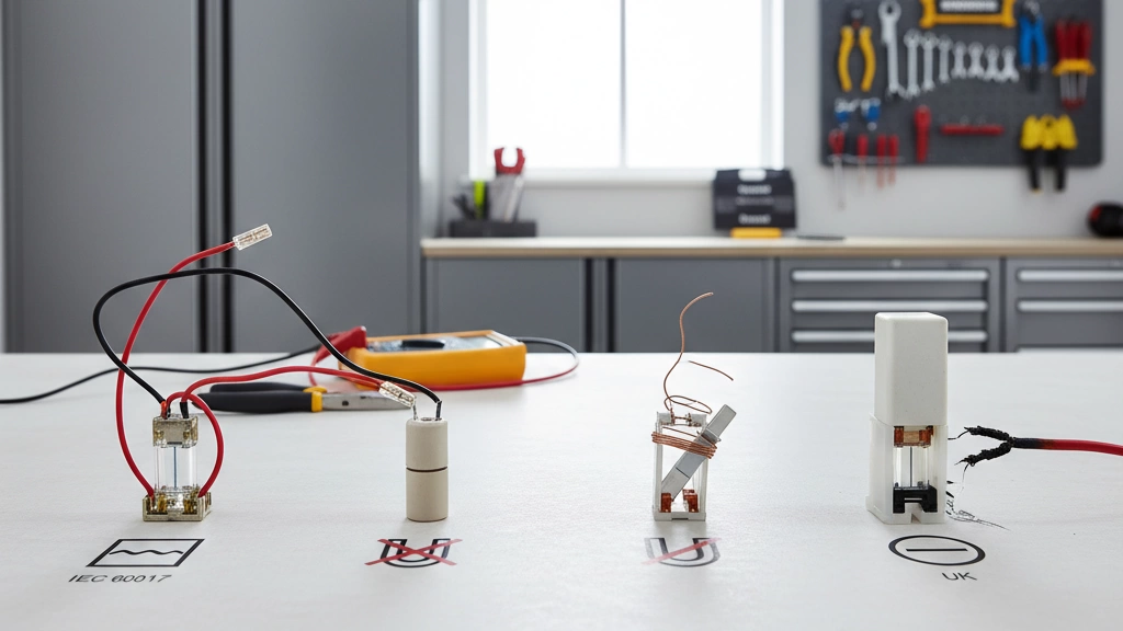
The Universal Fuse Symbol in Electrical Schematics
When you open a modern circuit diagram and see a small rectangle or capsule in series with a line, you’re almost always looking at the IEC electrical fuse symbol. If you work globally, this is the symbol you need to recognize first.
IEC 60617 Fuse Symbol: Appearance and Shape
Under IEC 60617, the standard fuse schematic symbol is simple and clean:
A straight conductor line (the circuit)
With a small rectangle or narrow capsule in series
Sometimes drawn as a plain rectangle, sometimes with slightly rounded ends
Visually, you can think of it as:
Line — [small rectangle] — line
No zigzags, no waves, no “S” shapes. Just a minimal, geometric shape on the conductor that clearly says “this is a protective fusible link.”
This style works well on dense electrical symbols charts and makes it easy to distinguish from resistors, circuit breakers, and other circuit protection symbols.
IEC S00106 Designation: What It Actually Means
The official code for the IEC fuse symbol is S00106 in the IEC 60617 database.
In practical terms:
S = Symbol
00106 = Unique ID for the general fuse symbol
It represents a generic fuse, independent of type (fast, slow, HRC, etc.)
Extra details like time-delay or HRC get added as text labels, not by changing the core symbol
So if you see S00106 referenced in a spec sheet or IEC electrical symbols chart PDF, you’re talking about the standard, universal IEC fuse symbol.
IEC Fuse Symbol in Single-Line Diagrams
On single-line diagrams (SLDs), you’ll usually see the fuse drawn in a very stripped-down way:
A single line representing the phase or pole
A small rectangle or block interrupting that line
A label like F1, FU1, or similar next to it
Typical usage in single-line:
Series with feeders, lighting circuits, motor circuits
Before or after a switch disconnector or contactors
Inside panel schedules and distribution diagrams
On SLDs, the goal is clarity at a glance, so the fuse symbol stays small, sharp, and consistent with IEC 60617.
IEC Fuse Symbol in Detailed Multi-Line Schematics
In detailed multi-line schematics, where each conductor is drawn, the IEC fuse symbol shows up more explicitly:
Each fused conductor gets its own little rectangle on the line
Multi-pole fuses appear as several rectangles aligned vertically or horizontally
Labels right next to the symbol give you the rating and type, for example:
F1 10A gG 500V
FU2 T2A 250V
Here’s what you’ll often see around the fuse symbol:
Reference designator: F, FU, F1, F2, etc.
Current rating: 2A, 10A, 32A…
Voltage rating: 250V, 500V, 690V…
Utilization category (like gG, aM) when needed
The symbol stays the same; the text does the heavy lifting to define the exact fuse you must install.
Where You’ll Most Often See the IEC Fuse Symbol
You’ll run into the IEC fuse symbol almost everywhere outside North America, especially in:
European industrial control panels and MCCs
House wiring diagrams in IEC countries
Solar PV, EV chargers, and inverter schematics
Automation and PLC wiring diagrams
International equipment manuals from brands like Schneider, ABB, Siemens, and my own global product lines
If your work touches global markets, treat the IEC 60617 / S00106 fuse symbol as your “default” circuit diagram fuse symbol. Learn it once, and you can read most modern industrial fuse schematics, fuse box diagram legends, and equipment labels with confidence.
ANSI / IEEE Fuse Symbol in American Diagrams
Classic ANSI fuse symbol (wavy / S-shaped)
In American electrical diagrams, the ANSI / IEEE fuse symbol is usually drawn as a wavy or S-shaped line in series with the conductor. Think of it as:
A short, curved “S” inside the line
Sometimes a squiggle between two straight line segments
This is different from the simple rectangle or box you’ll see in many IEC-style diagrams. In older industrial plans and some utility drawings, this “S” fuse symbol still shows up on panel schedules and protection one-line diagrams.
Key differences: ANSI fuse symbol vs IEC fuse symbol
If you’re switching between American and international drawings, here’s how the ANSI fuse symbol differs from the IEC fuse symbol at a glance:
Shape
ANSI / IEEE: wavy or S-shaped segment in the line
IEC (IEC 60617 S00106): simple rectangle/box in the line, sometimes with type codes (gG, aM, etc.)
Style
ANSI: more “hand-drawn” look, often curved
IEC: cleaner geometric shape, easy to standardize in CAD
Context
ANSI: common in North American utility, older industrial, and some OEM documentation
IEC: global default in modern multinational and export-oriented equipment
If you work with higher-voltage gear or replacement parts, you’ll often find IEC-based fuse symbols alongside real products like high-voltage fuses on data sheets and system drawings, even in US projects.
Side‑by‑side: IEC vs ANSI fuse schematic symbol
Here’s a quick mental comparison for circuit diagram fuse symbols:
ANSI:
Line — S-shaped squiggle — Line
No box outline
IEC:
Line — small rectangle — Line
Looks like a tiny “block” in the conductor
When you see both on an electrical symbols chart, remember: squiggle = ANSI, box = IEC.
Where legacy American fuse symbols still show up
You’ll still see the classic American fuse schematic symbol in:
Older plant one-line diagrams and relay coordination studies
Utility substation prints and traditional ANSI-based protection schemes
Legacy industrial control panel drawings that haven’t been updated to IEC
Some US-made OEM machines shipped with American-style documentation
If you’re retrofitting or expanding existing equipment, expect to meet these legacy American fuse schematic symbols and plan to cross-check them with updated IEC standards.
Reading mixed ANSI and IEC fuse symbols on one plan
Mixed symbol sets are common on global projects, especially when US-designed equipment is installed in IEC-based plants. To interpret mixed ANSI and IEC fuse symbols on the same plan:
Check the legend first
Look for an “electrical symbols chart” or “legend” section
Confirm which symbols follow ANSI, which follow IEC 60617
Match each symbol to its rating text
Text like F1, FU1, 10A, gG, T, HRC will confirm it’s a fuse
Watch for circuit breaker lookalikes
Breakers are usually drawn with a switch-like break in the line, not a squiggle or simple rectangle
Be consistent for modifications
When you add or change protection, stick to the standard already used on the sheet, or clearly label if you introduce IEC symbols into an ANSI drawing
If you’re unsure, tie the symbol back to the fuse holder symbol or physical fuse location shown in the panel schedule or equipment data. That’s the safest way to avoid confusing fuses with MCBs or other circuit protection symbols.
International Fuse Symbol Variations by Region
When you read electrical drawings from different countries, the fuse symbol (electrical) isn’t always the same. Standards evolved locally, so IEC, ANSI, BS, DIN, and JIS all have slightly different styles. If you work on global projects, you need to recognize these at a glance.
British Standard (BS 3939) Fuse Symbol Basics
Under BS 3939 (and later BS EN 60617), UK-style drawings mostly follow IEC, but older British schematics still show legacy symbols.
Typical BS fuse features:
Older BS symbol:
Often a small rectangle or a straight line with a short diagonal or bar, sometimes inside a protective outline.
It can look similar to a simple inline device, so context (label “F1”, rating nearby) is important.
Modern BS drawings:
Largely aligned with the IEC 60617 fuse schematic symbol – a small rectangle in series with the conductor, often labeled with current and fuse type (e.g., “F1 10A gG”).
You’ll see BS-style symbols mainly on UK plant, legacy distribution diagrams, and older panel schedules.
Old DIN (German) Fuse Symbol Style and Usage
Older DIN fuse symbols from German drawings can look quite different from IEC:
Legacy DIN style:
A narrow rectangle or a short, thick line on the conductor.
Sometimes a small “bump” or symbol shape inside a protective device outline to indicate a fuse-link.
Where you see it:
Old industrial plants, medium-voltage switchgear, and German-made control panels installed before full IEC harmonization.
Many modern German diagrams for MV/LV equipment (like ring main units or outdoor switchgear) now reference IEC symbol sets, especially when exported globally.
JIS (Japanese) Fuse Symbol Conventions
Japan uses JIS standards, which historically had their own look but are now more IEC-aligned.
Typical JIS fuse symbol points:
Older JIS symbols:
Small rectangular block in series, sometimes with a distinguishing mark or code near it.
Not as “wavy” or stylized as classic American symbols.
Modern JIS-based schematics:
Often mirror the IEC 60617 fuse symbol, especially in export products.
Expect clear labeling near the symbol:
“F1 5A”, “FUSE 10A”, or fuse type codes like “T2A 250V”.
If you’re reading Japanese PLC or inverter wiring diagrams, you’ll usually spot IEC-like fuse symbols paired with JIS notation.
Australian and New Zealand Fuse Symbol Variations
Australia and New Zealand follow AS/NZS standards that closely track IEC.
Key features:
Fuse symbol:
Almost always an IEC-style rectangular fuse symbol on line or single-line diagrams.
Where you see them:
Switchboards, residential switchgear, and industrial control panels across AU/NZ.
Any differences are usually in notation and abbreviations (e.g., “F” device tags, local rating presentation), not the symbol shape.
For medium-voltage gear or RMUs imported into AU/NZ, manufacturers typically publish drawings with IEC electrical symbols, keeping fuse symbols straightforward to interpret.
How to Quickly Tell Which Regional Standard a Symbol Follows
Here’s a simple way to spot the standard behind a circuit diagram fuse symbol:
IEC / BS / AU / NZ / Modern EU
Clean, simple rectangle in series with the conductor.
Often labeled like “F1 10A gG 500V”.
ANSI / Legacy American
Classic wavy-line or “S-shaped” fuse symbol.
Common in older US utility, industrial, and building drawings.
Old DIN / Older European
Block-like shapes or stylized inline symbols that don’t match the current IEC rectangle.
JIS
Often IEC-like today, but older prints may show subtly different blocks and notation with Japanese text or JIS references.
Check the title block and legend: they often mention “IEC 60617”, “ANSI/IEEE”, “BS”, “DIN”, or “JIS”, which immediately tells you which symbol set you’re dealing with.
Global Overview of Dominant Fuse Symbol Standards by Country
Broadly, the IEC fuse symbol now dominates low- and medium-voltage diagrams worldwide, especially in export equipment like switchgear, RMUs, and control panels.
Typical regional alignment:
IEC-based (rectangle fuse symbol)
Most of Europe (EU), UK (modern), Middle East, Africa, much of Asia, Australia, New Zealand, South America.
ANSI / IEEE-based (wavy-line fuse symbol)
United States, parts of Canada, some legacy systems in Latin America and Asia influenced by US standards.
Hybrid / Transition
Japan (JIS + IEC), older German/DIN systems, older British BS drawings.
When you’re comparing fuse vs circuit breaker symbols across multiple regions, this global context matters. Modern switchgear products, such as high-voltage circuit breakers or ring main units for 10 kV distribution networks, almost always use IEC-style symbols on their single-line diagrams, making them easier to interpret in international projects.
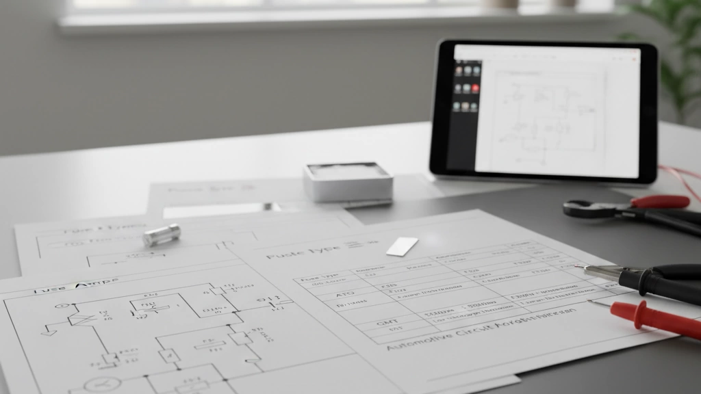
Fuse Type Symbols and Markings Next to the Fuse
When you look at an electrical fuse symbol in a circuit diagram, the shape tells you “this is a fuse,” but the markings next to it tell you what kind of fuse it is and how it behaves when a fault happens. If you work with house wiring, industrial control panels, or automotive systems, you need to read both the symbol and the text codes.
Fast-acting fuse symbol and markings
A fast-acting fuse (sometimes called “quick-acting” or “fast-blow”) is designed to open very quickly when the current goes over its rating.
Symbol in schematics:
Standard fuse symbol (IEC: small rectangle or box in the line; ANSI: wavy or S-shaped line)
Marked with codes like F, FF, or words like FAST or FUSE FAST.
Typical marking examples:
F2A 250V
FF500mA 125V
Use cases:
Sensitive electronics
Control circuits where you don’t want any overload time
If you see the standard fuse symbol with an F right before the current rating, treat it as fast-acting.
Time-delay (T) fuse symbol in schematics
Time-delay fuses (slow-blow fuses) allow short, harmless inrush currents (like motor starts) without tripping immediately.
Symbol: same basic fuse symbol.
Markings:
T before the current rating is the key: T10A 250V
Sometimes written as SLOW, SLO-BLO, or TIME-LAG.
What it means:
Can handle brief overloads
Will still open if the overload lasts too long
Whenever you see the fuse symbol with T in the code, expect a delayed reaction to overload.
High-rupturing capacity (HRC) fuse symbol and label codes
HRC fuses are built to safely interrupt very high fault currents without exploding or burning up. These are common in industrial and medium-voltage systems, often working alongside gear like a vacuum boundary circuit breaker.
Symbol:
Same fuse symbol, often with extra text: HRC or gG, gL, aR types.
Markings you’ll see:
HRC 63A 500V
gG 20A 690V
What HRC tells you:
High breaking capacity (can clear large short-circuit currents)
Used for higher energy networks and heavy loads
If the label includes HRC or a high breaking capacity value (e.g. 80kA), treat it as a high-performance protection fuse.
Cartridge fuse symbol in residential and industrial plans
A cartridge fuse is a cylindrical fuse used in many panels and equipment.
Symbol:
Standard fuse symbol plus note like CARTRIDGE, or just the rating and style.
Common markings:
10A 500V gG
NH 125A 500V
Where you see it:
Consumer units / distribution boards
Industrial control panels
Motor protection circuits
If the diagram shows a normal fuse symbol feeding main circuits with labels like NH, gG, or higher amps, that’s almost always a cartridge fuse.
Automotive blade fuse symbol in car wiring diagrams
In car wiring, the automotive blade fuse is the standard.
Symbol:
Small rectangle or box on the line, often labeled with “F” + number (F1, F5, etc.).
Some diagrams draw a stylized, squared U-shape to hint at the blade form.
Markings:
Just the current: 10A, 15A, 30A
Color-coded physically (red 10A, blue 15A, etc.).
Where:
Fuse box diagrams, under-dash panels, engine bay fuse blocks.
Match the fuse number in the legend to the symbol on the diagram, then to the actual blade fuse in the box.
Resettable PTC fuse symbol (polyfuse)
A resettable PTC fuse (polyfuse) limits current when hot, then resets when it cools down.
Symbol:
Looks like a resistor with a special note, or a fuse symbol with PTC written next to it.
Some standards show a rectangle with a diagonal line and PTC.
Markings:
PTC 0.75A
RXE050
Differences from standard fuse:
Does not permanently open; it self-resets.
Used in low-voltage electronics, chargers, small power supplies.
If you see PTC near a fuse-like component in a low-voltage circuit, assume resettable protection, not a one-time fuse.
Thermal fuse symbol and use in appliance diagrams
A thermal fuse trips based on temperature, not just current.
Symbol:
Often a fuse symbol with a small temperature indication or a tiny “thermometer” style mark.
Sometimes a series element marked TF, TCO, or THERMAL FUSE.
If you see a fuse symbol in series with a heating element and a temperature value (°C), that’s a thermal fuse.
How to read combined fuse type markings on one symbol
Most real fuses use combined codes, so you might see something like:
T5AL250V
F2A250V HRC
gG 32A 500V
Here’s how to break it down:
Part
Meaning
F / FF
Fast-acting / very fast-acting
T
Time-delay (slow-blow)
A / mA
Current rating
L, H, gG
Type / application / characteristic
V
Voltage rating
HRC
High-rupturing capacity
Tf XXX°C
Thermal fuse temperature rating
For example, T5AL250V typically means:
T – Time-delay (slow-blow)
5A – 5 ampere rated current
L – Often indicates low breaking capacity (depends on standard)
250V – Maximum working voltage
When you see multiple letters around the fuse symbol:
Read from left to right.
First letter: speed (F, FF, T).
Middle: current + any special type (L, H, gG, aR, etc.).
End: voltage rating and sometimes breaking capacity or temperature.
If you choose or replace a fuse based only on the amp rating and ignore these markings, you risk nuisance trips or, worse, unsafe operation under fault conditions.
Common Fuse Symbol Mistakes and Lookalikes
Even experienced engineers sometimes misread a fuse symbol on an electrical drawing. That can lead to choosing the wrong protection device, wrong wiring, or compliance issues. Here’s how I clearly separate fuse symbols from similar electrical symbols on real-world schematics.
Fuse symbol vs circuit breaker symbol
On most modern diagrams:
Fuse symbol (IEC)
Simple straight line with a small rectangle or oval in series.
Often labeled with a rating like “10A / 250V” or a code like “T5AL250V”.
Circuit breaker symbol (MCB / MCCB)
Shows a switch-like element: a break in the line with a movable contact, sometimes in a rectangle.
Often marked as CB, MCB, MCCB and may show trip curve or breaking capacity.
Key differences:
A fuse is just a passive link that melts; the symbol is simple and fixed.
A circuit breaker opens mechanically and can be reset, so its symbol looks like a switch.
On panel and switchgear drawings, circuit breaker symbols will often be tied to breaker data, trip units, or protection curves; if you’re working with low-voltage or medium-voltage breaker and switchgear diagrams, don’t assume every protection symbol is a fuse.
If the symbol looks like a switch or toggle, treat it as a breaker, not a fuse.
Fuse symbol vs resistor symbol confusion in older diagrams
On legacy or hand-drawn diagrams, fuse symbols and resistor symbols can look surprisingly similar:
Old fuse symbol (American/legacy)
Often a wavy or S-shaped line in series.
Resistor symbol
In American style: zigzag line.
In IEC style: rectangle.
How to tell them apart on older drawings:
Check labels:
Fuses: F, FU, F1, F2, etc., and a current rating.
Resistors: R, VR, R1, R2, etc., and a resistance value (Ω, kΩ).
Check context:
If it’s right on the line side of a load, transformer, or control circuit, it’s likely a fuse.
If it’s part of a voltage divider, bias network, or filter, it’s a resistor.
Never decide based only on the squiggle shape; the text around it usually gives it away.
How beginners commonly misread fuse-related symbols
New users of circuit diagram fuse symbols often:
Assume every protection symbol is a circuit breaker because that’s what they see in home panels.
Treat fuse + switch combinations as just a switch.
Ignore the markings next to the symbol (T, F, HRC, rating codes), missing the type of fuse completely.
Confuse PTC resettable fuse symbols or thermal fuse symbols with sensors or resistors.
Typical beginner traps:
Seeing “F1 5A” and thinking it’s a 5 A load, not a 5 A fuse.
Misreading an HRC fuse symbol as a generic disconnect.
Reading “T2AL250V” and not realizing “T” means time-delay (slow-blow).
Real-world examples of wrong symbol identification and consequences
A few examples I’ve seen play out in real installations:
Fuse vs breaker mix-up
A technician thought a fuse symbol was a breaker and expected it to reset. The actual fuse kept blowing, so they kept powering up a fault, which damaged a power supply and extended downtime.
Resistor vs fuse confusion in a legacy drawing
A maintenance team replaced a “mysterious component” drawn as a wavy line with a resistor instead of the fuse it was meant to be. The circuit lost its safety protection and later failed dangerously under a short.
Wrong fuse type (fast vs time-delay)
A time-delay fuse symbol (T fuse) was misread as a standard fast-acting fuse. The replacement blew on every motor start, leading to “mystery faults” and unnecessary service calls.
When the symbol is wrong or misread, the most common consequences are:
Most professional drawings include an electrical symbols chart. If you’re unsure, refer to it first.
If you apply these checks every time, you’ll quickly stop mixing up fuse symbols with circuit breakers, resistors, or other protection devices.
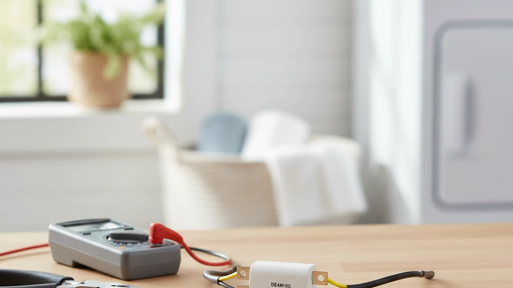
Reading Fuse Ratings and Codes on Electrical Schematics
When you see a fuse symbol on an electrical diagram, the small text next to it is just as important as the symbol itself. If you read those codes correctly, you’ll pick the right fuse and avoid nuisance trips or dangerous faults.
What ratings like 10A, 250V really mean
You’ll usually see something like: 10A 250V
10A = maximum current the fuse can carry continuously without blowing (at a defined temperature).
250V = maximum system voltage where the fuse can safely interrupt a fault without arcing across.
Key point: A fuse rated 10A 250V can be used at lower voltages (e.g. 24V, 110V), but not at higher ones (e.g. 400V).
Breaking down codes like T5AL250V
A common code on schematics and on the fuse body is: T5AL250V
Here’s what each part means:
Code part
Meaning
T
Time-delay (slow-blow)
5A
Rated current (5 amperes)
L
Breaking capacity: Low (L)
250V
Rated voltage (250 volts AC/DC, per datasheet)
Other common letters:
F = Fast-acting (quick-blow)
M = Medium time-lag (less common)
H or HBC/HRC = High breaking capacity
Always cross-check with the datasheet for local standards (IEC, UL, etc.).
Current rating vs breaking capacity
These two get mixed up a lot, but they’re very different:
Current rating (In)
Normal continuous current the fuse can handle.
Example: 10A fuse in a 6–8A circuit.
Breaking capacity (Icn or Icu)
Maximum fault current the fuse can safely interrupt.
Example: 80kA HRC fuse in high short-circuit industrial systems.
Rule: Never install a fuse where the possible short-circuit current is higher than its breaking capacity.
For higher fault levels, we’d pair correctly rated fuses with properly selected high-voltage switchgear or switch isolators in the upstream distribution so the protection chain stays safe.
How voltage rating affects the symbol and the part
The symbol on the schematic stays almost the same, but the marking beside it matters:
Low-voltage AC (230/400V)
Marking like: T16A 250V HRC
Use proper cartridge or NH fuses with matching holders.
DC systems (solar, battery, EV)
Look for DC in the marking, e.g. 20A 1000V DC.
DC-rated fuses have different construction to break arcs reliably.
High-voltage systems
Specialized fuses within switchgear; match both kV rating and kA breaking capacity.
Never “upgrade” voltage rating by guesswork. A 250V fuse is not automatically OK at 500V.
Typical rating formats in house, industrial, and automotive diagrams
You’ll see slightly different styles depending on the application:
1. House wiring and appliances
Common formats:
F2A 250V – fast 2 A, 250 V
T10A 250V – time-delay 10 A, 250 V
T1.6AL250V – time-delay 1.6 A, low breaking capacity, 250 V
Used in:
Consumer units (older fuse boards)
Plug-top and appliance fuses
Control modules in HVAC, boilers, etc.
2. Industrial panels and machinery
Markings often include more detail:
gG 32A 500V 120kA – general-purpose, 32 A, 500 V, 120 kA breaking capacity
aR 80A 690V – semiconductor protection fuse, 80 A, 690 V
T6.3A 250V HRC – time-delay, 6.3 A, high breaking capacity
You’ll see these next to fuses feeding motors, control transformers, and in panel schedules on industrial drawings.
3. Automotive and mobile equipment
Usually simplified:
15A or 10A next to a blade fuse symbol
Sometimes voltage is implied (12V, 24V, 48V systems)
Example formats:
Application
Typical marking
Car fuse box
10A, 15A, 20A
Truck/bus
20A, 30A at 24V
EV/HEV high-voltage
40A 450V DC, 150A DC
Automotive diagrams often rely on:
Color of blade fuse (e.g. blue = 15A)
Legend in the fuse box diagram to match rating and function
Quick checklist when reading fuse codes on schematics
Before choosing a fuse, I always confirm:
Fuse type: Fast (F) or time-delay (T)?
Current rating: Does it match the load and inrush?
Voltage rating: Equal or higher than system voltage?
Breaking capacity: High enough for the worst-case fault?
Standard: Matches IEC / UL / automotive requirements in your country?
If you follow those five points, most fuse selection mistakes disappear before you even order parts.
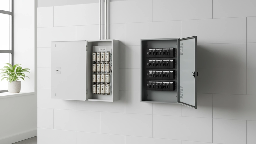
Fuse Symbols on Real Equipment and Labels
Fuse symbol on home consumer units and breaker panels
On modern consumer units (breaker panels), the electrical fuse symbol usually appears:
Next to miniature circuit breakers (MCBs) or switch‑disconnectors that include fuse protection.
On the front door label or panel schedule to show which circuits are fuse‑protected (lighting, sockets, EV charger, HVAC, etc.).
As a small IEC fuse symbol (a simple rectangle or bar with a line through it) near each fuse holder or combined switch‑fuse.
If you’re upgrading or specifying panels, make sure the printed legends clearly match the symbols on the schematic and the devices themselves. When we design switch‑fuse and switch‑disconnector assemblies, we follow IEC symbol conventions so that the device label, panel drawing, and one‑line diagram all tell the same story. For example, a fused isolator on a main incomer will be shown consistently across schematics and product pages for our switch‑disconnector solutions: industrial switch‑disconnectors and isolation devices.
Quick tips for home panels:
Look for the fuse symbol right by the circuit name (e.g. “Sockets – 20 A” with a fuse icon).
Check if the symbol matches the actual device:
Fuse carrier or cartridge -> fuse symbol
Toggle breaker only -> circuit breaker symbol (not a fuse).
Industrial control panel labels and fuse symbols
In industrial control panels, fuse symbols and labels are more detailed because there are more protection points:
Each fused circuit (control transformer, motor branch circuit, PLC supply, IO cards) will have:
A fuse symbol on the schematic (IEC, ANSI, or mixed).
A matching tag on the physical fuse holder (e.g. F1, F2, F3).
Door labels and internal marker strips often use the IEC 60617 fuse symbol plus a designation like “F1 – 4 A gG 500 V”.
Good practice:
Always cross‑check the device tag on the panel (F1, F2, etc.) with the schematic. The symbol tells you it’s a fuse; the tag tells you exactly which one.
In multi‑standard plants (e.g. European machines installed in North America), you may see IEC fuse symbols on the drawings but mixed with ANSI‑style tags in documentation. Rely on the label + tag combo, not just the shape.
Automotive fuse box legends and symbols in manuals
In cars, the electrical fuse symbol appears in three main places:
On the plastic fuse box cover:
A fuse icon plus a description like “RADIO 10 A” or a pictogram (headlamp, wiper, etc.).
Inside the owner’s manual:
A fuse box diagram legend showing fuse locations, ratings, and an automotive blade fuse symbol.
On some dashboards or service labels under the hood:
Small fuse icons marking key protection points (e.g. ABS, ECU).
To match what you see:
The fuse symbol in the manual usually represents an automotive blade fuse, even if the icon is very simple.
Compare the position number in the legend (e.g. F10) to the mold marking in the fuse box, then check the rating printed on the fuse body (e.g. 15).
If you’re troubleshooting, confirm that the symbol is a fuse, not a relay – relays are usually shown as a square/rectangle with internal contacts, not the basic fuse icon.
Matching a schematic fuse symbol to a physical fuse holder
When you’re on site, the key is to connect the drawing to the hardware quickly and safely:
Read the schematic:
Find the fuse symbol on the circuit diagram (IEC bar/rectangle or ANSI wavy‑line).
Note the reference designator (F1, FU1, F101, etc.).
Note the rating and type next to it (e.g. 10 A gG 500 V, T2A 250 V, HRC).
Find the same reference in the panel:
Look for the same label printed or engraved near the fuse holder or switch‑fuse.
On DIN‑rail mounted holders, the tag might be on a clip or marker strip above or below the device.
Confirm visually:
Check the physical fuse carrier matches the type indicated:
Cartridge fuse -> cylindrical or cartridge holder.
HRC fuse -> larger, often with ceramic body.
Blade fuse -> flat, color‑coded plastic.
This simple three‑step method avoids swapping the wrong fuse, especially in dense industrial panels.
Using real‑world labels to double‑check schematic interpretations
If you’re ever unsure what a fuse symbol electrical actually represents, use the real equipment as your final check:
Compare labels:
Symbol + tag on schematic
Tag + sticker/engraving on the device
Printing on the fuse body (rating, type code)
Verify ratings:
The schematic might say “F3 6 A gG 500 V”. The fuse body should show something very close to that rating and type.
Cross‑validate standards:
Mixed IEC / ANSI / local symbols are common in global projects. If the symbol style confuses you, trust the text: “F”, “FU”, rating (A, V), and type (gG, T, F, HRC, etc.) tell you it’s a fuse.
Good habits:
Never rely on the symbol shape alone, especially on older or mixed‑standard drawings.
Use labels, legends, and physical markings as a package. When those three agree, you can be confident you’ve identified the right fuse and the right protection level.
FAQs About Electrical Fuse Symbols
What is the standard fuse symbol used in most electrical schematics?
In modern drawings, the IEC fuse symbol is the most common worldwide. It’s usually shown as a small rectangle or capsule shape in series with a conductor, often with a label like “F1”, “F2”, etc.
You’ll see this style in:
Industrial control panels
Building services drawings
Most OEM equipment manuals
If you’re working with international projects or multi-country teams, this is the symbol style you’ll deal with most.
Why do multiple different fuse symbols exist worldwide?
Different regions built their own standards over time:
IEC for Europe and most of the world
ANSI / IEEE for North America
BS / DIN / JIS variants for the UK, Germany, Japan, etc.
Each standards body defined its own electrical symbols chart, and many legacy drawings still follow older rules. That’s why you’ll see:
The IEC capsule-style symbol on newer plans
The classic wavy or S-shaped fuse symbol on US legacy drawings
Global work means we simply have to recognise both.
Do house wiring and car wiring use the same fuse symbol?
Not always.
House wiring / building plans
Usually use the IEC rectangular fuse symbol or show the MCB / breaker symbol instead (since many homes now use breakers, not fuses).
Car wiring / automotive diagrams
Use more specific icons:
Automotive blade fuse symbol (resembling the physical blade fuse shape)
Cartridge-style icons in some OEM manuals
So yes, they both show “fuses”, but the circuit diagram fuse symbol in automotive documents is often more pictorial and tailored to blade fuses and fuse boxes.
How do I quickly tell a fuse symbol from a circuit breaker on a diagram?
Use these quick checks:
Fuse symbol (electrical fuse symbol IEC):
Simple shape (small rectangle or capsule) in series with the line
Usually labelled “F1”, “F2” etc.
No moving mechanism drawn
Circuit breaker symbol (MCB vs fuse symbols):
Often shows a switch-like element, sometimes with a hinge or contact representation
Labels like “Q1”, “CB1”, or “MCB”
On some ANSI drawings, may look like a switch with extra markings
If you see anything that clearly looks like a switching mechanism, assume circuit breaker, not a fuse.
What’s the best way to learn and remember the main fuse symbols?
Here’s what I recommend to engineers and technicians we work with:
Focus on 3 main families first:
IEC 60617 fuse symbol (modern global standard)
ANSI / American fuse schematic symbol (wavy/S-line)
Automotive blade fuse symbol (for car wiring schematics)
Practice with real documents:
Grab a fuse box diagram legend from your car manual
Look at your home consumer unit / panel schedule fuse symbol legends
Review one or two industrial fuse schematic examples
Build your own mini “electrical symbols chart PDF”:
Take screenshots or sketches of the key fuse, breaker, and resistor symbols
Keep it on your phone or laptop for quick reference on-site
The more often you match symbols on a schematic to the actual fuse holders and panels in front of you, the faster the shapes will stick in your memory.
If you’re building or standardising documentation at scale, it also helps to align your drawings to one clear standard and document that decision clearly in your internal design rules and company guidelines so teams across regions all read the same symbols the same way.
If your GE dryer is tumbling but blowing ice-cold air—or suddenly won’t start at all—there’s a very good chance the thermal fuse just sacrificed itself to protect your home. The good news?On most General Electric dryers, a bad thermal fuse is one of the easiest and cheapest fixes you can do yourself… if you know the right part number, the exact location, and how to test it with […]
What Is a Fuse Box and How Does It Work? A fuse box is an older style of electrical panel that protects your home’s wiring by using fuses instead of modern circuit breakers. You’ll usually find it in a basement, garage, utility room, or near the electrical meter. Visually, a fuse box is: Older panels from brands like Sylvania, Zinsco, and […]
What Does the Thermal Fuse Do and Why It Blows The thermal fuse in a GE electric dryer is a crucial safety device designed to prevent fires. Think of it as the dryer’s smoke detector—it shuts off the heat if things get too hot inside. When the dryer’s temperature rises beyond safe limits, the thermal […]
We use cookies to enhance your browsing experience, serve personalised ads or content, and analyse our traffic. By clicking "Accept All", you consent to our use of cookies.