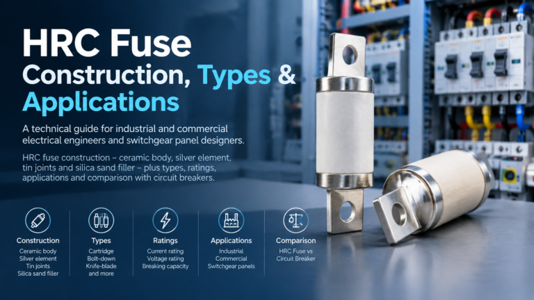
HRC Fuse: Construction, Types & Applications
How an HRC fuse is built and why it can interrupt 100 kA: element, tin joints and silica sand filler, the main types, the ratings to check, and HRC versus breaker.
Read More
A drop out fuse cutout is the device you see hanging open on a distribution pole after a fault — and that visible, fallen tube is not a side effect of the design, it is the design. Understanding the drop-out fuse cutout working principle means understanding three connected events: the fuse element melts, the arc is blown out by gas generated inside the tube, and the tube then swings down under gravity to leave a clear isolating gap. This guide explains each step, describes the main parts, compares the two fuse link technologies used inside the cutout, and covers the selection and coordination rules that decide whether the right fuse blows when a fault happens.
A drop-out fuse cutout — also called a dropout expulsion fuse or, in the field, simply a cutout — is an outdoor overcurrent protection device for overhead distribution systems. It is widely applied from about 2.4 kV up to 38 kV, most commonly at 11 kV, 22 kV, and 33 kV, and its primary job is to protect pole-mounted distribution transformers, capacitor banks, and tapped feeders. Its second job, equally valued by utilities, is to act as a visible isolating switch: once the tube has dropped, a crew can see that from the ground that the line is broken.
| Part | Function |
|---|---|
| Insulator body | Mounts the assembly on the cross-arm and insulates the live parts from the earthed structure; commonly porcelain or polymer housed |
| Fuse holder (the tube or “door”) | Carries the replaceable fuse link, forms the arc-quenching chamber, and pivots on a hinge so it can drop open |
| Contacts, hinge, and mounting bracket | Complete the circuit when closed, release the tube when the link melts, and hold the assembly rigidly on the pole |
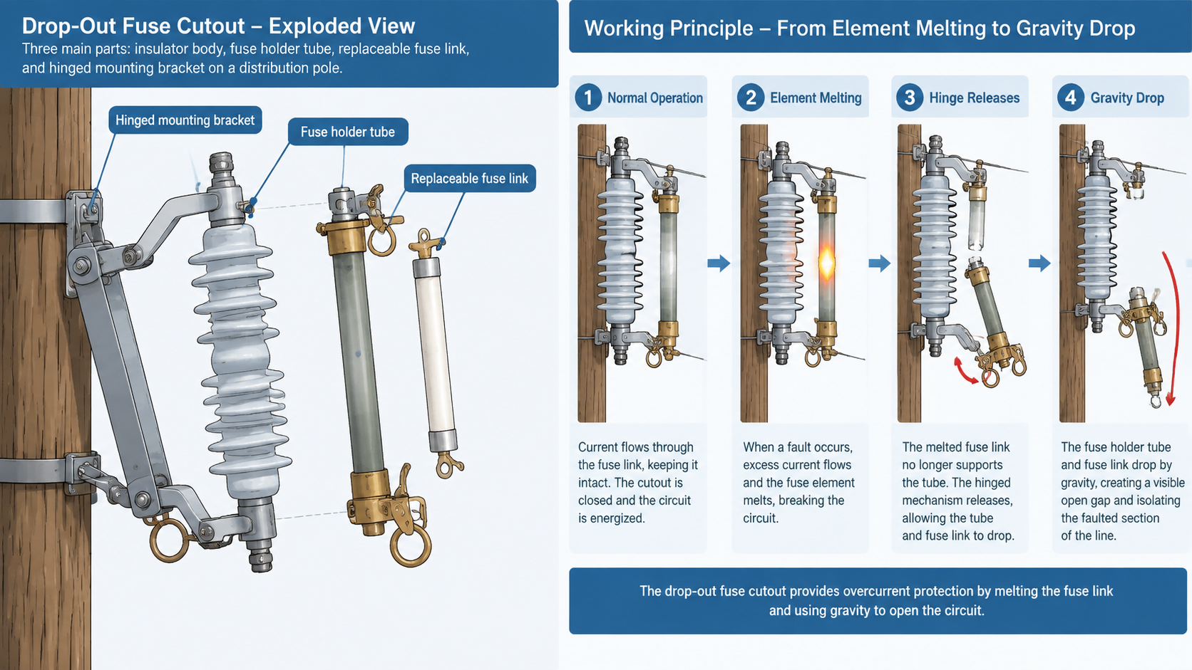
The sequence above is why these devices are called expulsion fuses: the arc is not absorbed or cooled in place, it is expelled. It also explains the characteristic report heard when a cutout operates, and why the tube must be free to swing without obstruction.
Expulsion clears the fault current, but the drop is what makes the device practical for a distribution network.
| Fuse link technology | How it clears | Key characteristic |
|---|---|---|
| Expulsion type | Gas generated by the tube lining blasts the arc out at current zero | Low cost, wide availability, visual drop-out indication; does not limit fault current |
| Current-limiting type | Element melts inside a filler such as silica sand, which quenches the arc and forms an insulating mass | Very fast operation that cuts off the fault before peak current; used where let-through energy must be limited |
Where the available fault current is high — typically beyond the order of 10–16 kA — a cutout with an expulsion link is often paired with a backup current-limiting fuse. The expulsion cutout handles low and moderate fault duties with easy visual indication, while the current-limiting fuse constrains the energy let through to the protected transformer or cable.
The cutout and the link are selected separately, and both have to be right. A RW12 high voltage fuse rated for 12 kV service is not the same specification as a 33 kV cutout, even though the working principle is identical.
The hinge geometry is not cosmetic. A cutout is mounted at an angle so the holder swings clear when the link releases, and the open gap has to meet the phase-to-phase and phase-to-earth clearance required at that voltage. Before commissioning, check that the mounting bracket is rigid, that the tube swings freely with no binding or corrosion at the hinge, that phase clearances and the vent direction are correct, and whether animal guards are needed where wildlife contact is a known cause of faults.
The drop-out fuse cutout working principle is a chain of three events: the calibrated element melts under fault current, the tube’s lining generates de-ionising gas that extinguishes the arc at current zero, and the released holder falls open to leave a visible, safe isolating gap. It is an old design and a simple one, and that simplicity is exactly why it still protects most overhead distribution transformers in the world. Choose the cutout by voltage and breaking capacity, choose the link by continuous current, inrush tolerance, and coordination — and verify that the hinge still moves freely at every inspection.
Fault current melts the fuse link inside the holder, which creates an arc. Heat from the arc generates de-ionising gas from the tube lining, and the gas blast extinguishes the arc at the next current zero. With the link gone, the holder swings down on its hinge and hangs open, isolating the circuit.
A drop-out fuse cutout is a specific form of expulsion fuse. The expulsion principle describes how the arc is cleared — by gas blast — while the drop-out mechanism describes the gravity-operated holder that provides visible isolation after operation.
Yes, but its capacity is limited and depends on the cutout and link ratings. Where the available fault current exceeds that capability, a backup current-limiting fuse is used to limit the energy let through.
Primarily to protect pole-mounted distribution transformers, capacitor banks, and tapped feeders on overhead medium-voltage networks, and to provide an obvious visible isolating point for maintenance crews.
Size the link above the maximum continuous load with margin for normal overload and ambient temperature, confirm it will pass transformer inrush without melting, and verify that its time-current curve coordinates with the upstream protective device.
Usually because the hinge or contact is corroded or mechanically stiff, because the mounting angle is wrong, or because the assembly is obstructed — one of the most common findings during cutout inspection.