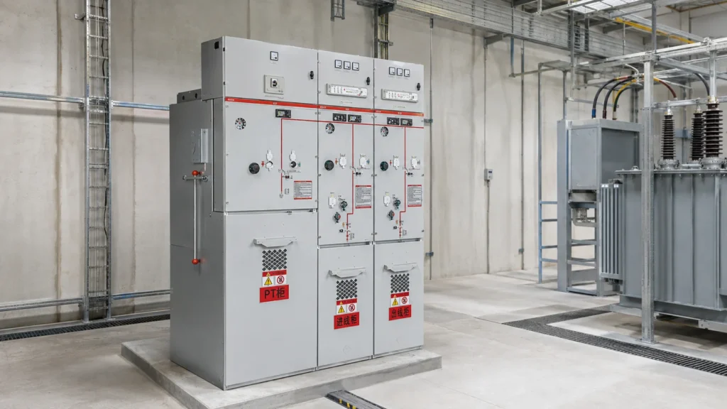
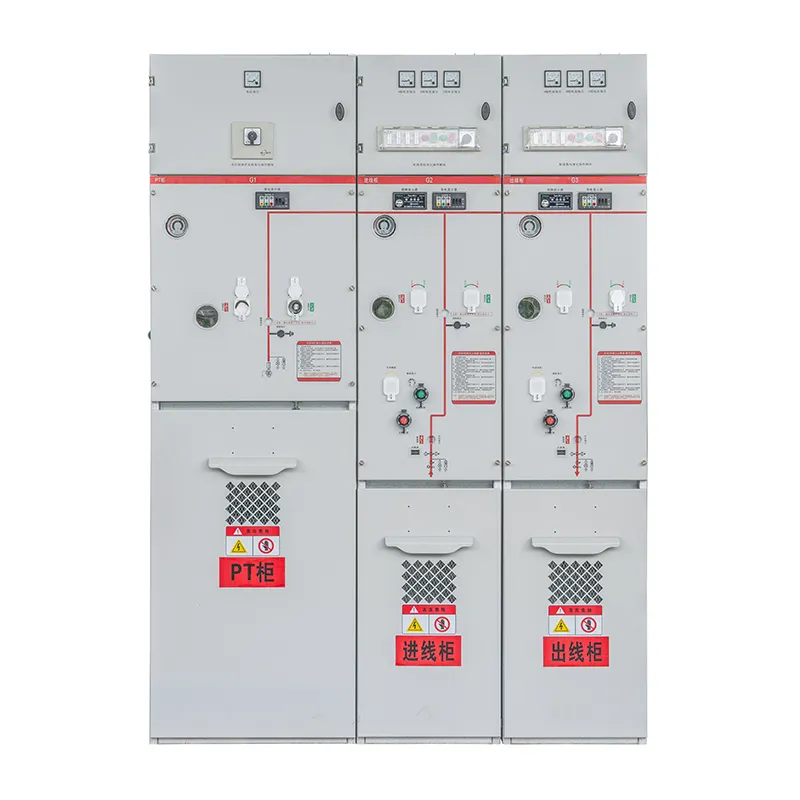
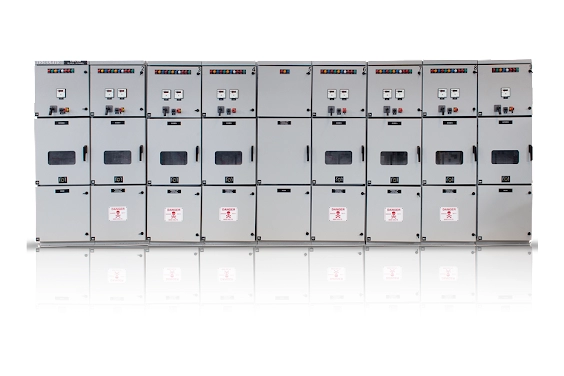
A Ring Main Unit (RMU) is a compact, factory-assembled form of medium-voltage switchgear used at load connection points in a ring or loop distribution network. It switches, isolates, and protects sections of the network while allowing electricity to reach loads from an alternative direction when a cable section is unavailable. This combination of compact construction and supply continuity is why RMUs are common in urban substations, commercial buildings, industrial sites, renewable-energy projects, and compact secondary substations.
This guide explains the components of an RMU, the ring main unit working principle, how to read a basic ring main unit diagram, and how an RMU differs from general medium-voltage switchgear. It also gives practical criteria for specifying an RMU system for a project.
What Does a Ring Main Unit Do?
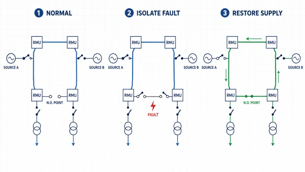
An RMU provides controlled connection points on a medium-voltage distribution ring. In a typical arrangement, two switching ways connect the incoming and outgoing ring cables, while a third way supplies and protects a transformer or another local load. Operators can open switches on both sides of a faulty cable section, isolate that section, and restore supply to healthy parts of the ring from the other direction.
Describes the network arrangement, not the physical shape of the cabinet. The network may be designed as a closed loop but operated with one point normally open. This enables straightforward fault isolation and supply transfer without operating the entire network as a permanently closed ring.
Why Is RMU Used in Power Distribution?
If you are asking why is RMU used, the short answer is continuity, space efficiency, and safer sectionalizing. A radial feeder has only one normal supply path; a fault upstream can interrupt every downstream load. A ring network gives each RMU access to two possible supply directions, subject to the network’s protection and operating scheme.
Improved service continuity: healthy sections can often be re-energized after the faulty section is isolated.
Compact footprint: integrated functional units need less space than many conventional panel lineups.
Safe isolation: interlocks, earthing switches, position indicators, and enclosed live parts support controlled switching procedures.
Fast installation: factory-assembled modules reduce site assembly and simplify integration into kiosks and compact substations.
Automation options: motorized mechanisms, sensors, fault indicators, and communication devices can support remote supervision and feeder automation.
These advantages make an RMU system useful where outage duration matters and installation space is limited. Typical sites include residential developments, hospitals, airports, data centers, shopping complexes, factories, wind farms, solar plants, and utility distribution nodes.
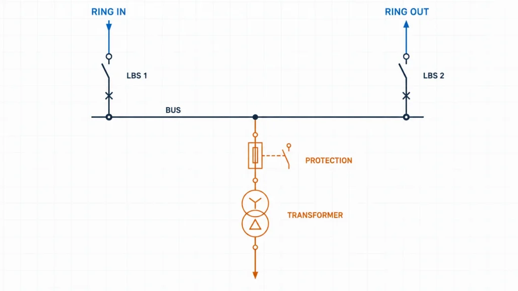
Ring Main Unit Diagram: A Typical Three-Way Layout
A basic ring main unit diagram is usually a single-line diagram rather than a detailed wiring drawing. A common three-way RMU contains two ring feeder ways and one transformer feeder way:
Source A ---- [LBS 1] ---- BUSBAR ---- [LBS 2] ---- Source B
                              |
                        [CB or Switch-Fuse]
                              |
                         MV/LV Transformer
                              |
                           LV Loads
LBS 1 and LBS 2 are load break switches for the two sides of the ring. The tee-off way normally uses a circuit breaker with a protection relay or a switch-fuse combination, depending on transformer rating and the required protection scheme. An earthing switch is provided for safe cable or feeder grounding after isolation. Current transformers, voltage indicators, fault passage indicators, and metering devices may also be included.
The exact single-line diagram must be matched to the network study. Four-way and extensible arrangements can add transformer feeders, metering ways, bus sections, or future connections. Never assume that every three-way RMU has the same protection functions simply because the front panel looks similar.
Main Components of an RMU System
Although designs vary by insulation technology and manufacturer, most RMUs combine the following functional elements:
Component
Primary function
Selection consideration
Load break switch
Makes and breaks normal load current on ring feeders
Rated current, making capacity, endurance, and operating mechanism
Circuit breaker or switch-fuse
Protects the transformer or outgoing feeder
Fault level, relay coordination, transformer rating, and breaking capacity
Busbar
Connects the functional ways inside the unit
Continuous current and short-time withstand rating
Earthing switch
Grounds an isolated cable or circuit for maintenance
Making capacity, interlocking, and indication
Cable compartment
Provides screened cable terminations and test access
Cable size, connector interface, phase spacing, and accessibility
Protection and monitoring
Detects faults and provides trip, indication, or remote data
Protection functions, sensor type, auxiliary power, and communication protocol
Enclosure and insulation system
Separates live parts from people and the environment
Indoor/outdoor use, internal arc class, IP rating, and insulation medium
RMUs may use air, gas, solid dielectric, or a hybrid insulation design. Vacuum interrupters are widely used for circuit-breaking functions, while the enclosure and primary insulation approach depend on the selected product. A brand-specific phrase such as ring main unit Schneider may lead you to one supplier’s product family, but the project decision should be based on ratings, tested performance, service conditions, interfaces, documentation, and lifecycle support ot the brand name alone.
Ring Main Unit Working Principle
The ring main unit working principle is based on switching and sectionalizing a looped feeder while coordinating protection for outgoing loads. Under normal conditions, the two ring switches carry current along the distribution route and the tee-off way feeds a transformer or local circuit.
Normal service: the designated switches are closed according to the approved network configuration. Power reaches the load from the normal supply direction.
Fault detection: protection devices or fault indicators identify a cable or feeder fault. A circuit breaker may trip automatically when its protection zone is affected.
Section isolation: authorized operators identify the faulty section, open the appropriate switches at both ends, verify isolation, and apply earthing according to the switching procedure.
Supply restoration: after checks and protection coordination, healthy sections can be supplied from the alternative side of the ring by changing the normally open point.
Repair and normalization: the isolated section is repaired and tested before the network is returned to its approved normal arrangement.
An RMU does not, by itself, guarantee uninterrupted power. Restoration depends on the network topology, available source capacity, protection settings, automation level, cable condition, and operating procedures. Switching must be performed by qualified personnel under an approved safety program.
Ring Main Unit vs Switchgear: What Is the Difference?
The clearest way to understand ring main unit vs switchgear is that switchgear is the broad category, while an RMU is a specialized, compact type of medium-voltage switchgear optimized for ring distribution. It is therefore inaccurate to treat them as completely separate equipment classes.
Criterion
Ring Main Unit
General MV switchgear lineup
Primary role
Ring feeder switching, sectionalizing, and local transformer/feeder protection
Main distribution, incomers, feeders, bus coupling, motors, capacitors, and complex protection
Typical construction
Compact, factory-integrated, often fixed functional ways
Multiple panels; fixed or withdrawable switching devices
Footprint
Usually smaller
Usually larger for an equivalent number of functions
Protection complexity
Simple to advanced, depending on breaker and relay options
Well suited to advanced protection, metering, and control schemes
Expansion
Fixed or extensible, depending on design
Often more flexible for large future lineups
Typical application
Secondary distribution and compact substations
Primary substations, plants, and systems with many or complex feeders
Choose an RMU when the network requires a compact ring node with a modest number of ways and straightforward transformer or feeder protection. Choose a broader switchgear lineup when you need numerous feeders, high bus ratings, withdrawable breakers, extensive metering, complex interlocking, or frequent future expansion. For a complete project, RMUs and other switchgear may be used at different levels of the same distribution system.
Common RMU Types and Insulation Options
Gas-insulated RMU
Primary components are enclosed in a sealed gas tank, allowing a compact footprint and strong resistance to dust, humidity, and contamination. Buyers should verify the insulating gas, leakage monitoring, environmental requirements, and end-of-life handling.
Solid-insulated RMU
Solid dielectric materials encapsulate or shield primary live parts. This approach can avoid insulating gas but requires careful evaluation of interfaces, partial-discharge performance, heat dissipation, repairability, and recycling.
Air-insulated RMU
Air provides the principal insulation between primary parts. Air-insulated designs can be straightforward to inspect, though they commonly require more space and greater control of environmental contamination.
Vacuum switching
Vacuum describes the arc-interruption medium inside the interrupter, not necessarily the insulation method for the entire cabinet. A vacuum circuit breaker can therefore be used within air-, gas-, or solid-insulated equipment.
How to Select the Right Ring Main Unit
Start with the power-system study and the applicable standards, then translate the results into a written technical specification. At minimum, confirm:
highest system voltage, frequency, insulation level, and earthing method;
rated normal current and short-circuit making, breaking, and short-time withstand duties;
required number of ring, transformer, metering, and spare ways;
circuit breaker versus switch-fuse protection and relay coordination;
indoor or outdoor installation, ambient temperature, altitude, humidity, pollution, and IP rating;
internal-arc classification, interlocks, earthing provisions, pressure relief, and cable-test access;
cable sizes, connector types, phase arrangement, trench or plinth dimensions, and grounding interface;
manual, motorized, or automated operation, plus SCADA and communication requirements;
type-test evidence, routine tests, drawings, manuals, spare parts, training, and service support.
For a 10 kV project, compare the XGN15-12F/T630-20 10 kV Ring Main Unit with the 10 kV Ring Main Unit. The correct choice depends on the approved single-line diagram, current and fault ratings, insulation approach, environmental conditions, protection philosophy, and utility requirements.
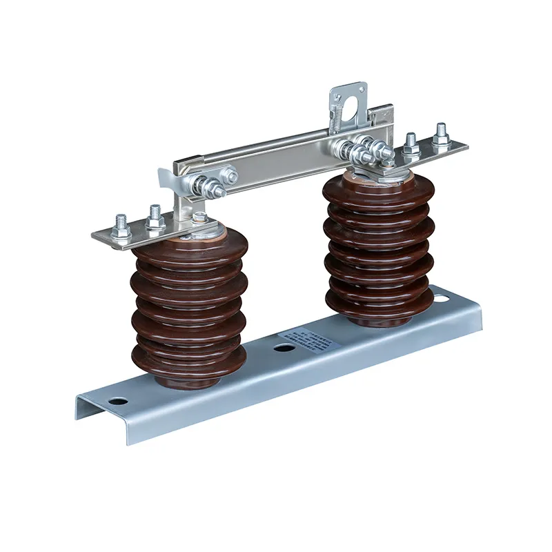
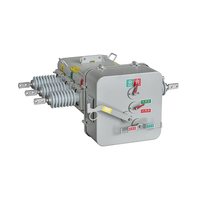
Related equipment may also be needed outside the RMU. A GW9 high-voltage isolator switch provides no-load isolation in suitable outdoor applications, while the ZW32-12F outdoor vacuum circuit breaker supports outdoor feeder switching and protection. These products perform different functions and should only be combined through a coordinated system design.
Installation, Testing, and Maintenance Essentials
Before energization, check the foundation, clearances, enclosure condition, cable terminations, phase sequence, grounding continuity, mechanical interlocks, indicators, auxiliary circuits, protection settings, and communication links. Perform the required insulation, functional, timing, and protection tests in accordance with the manufacturer’s instructions and the project commissioning plan.
Maintenance intervals should follow the manufacturer, utility rules, operating duty, and site environment. Routine work may include visual inspection, condition monitoring, mechanism checks, cleaning accessible insulation, verifying indications and interlocks, checking heaters or gas-density devices where applicable, testing protection, and reviewing event records. Never defeat an interlock or operate equipment outside its rated duty.
A Ring Main Unit is compact medium-voltage switchgear designed to switch, isolate, and protect distribution nodes while supporting supply restoration through a ring network. Its value comes from the complete system: correct topology, suitable ratings, coordinated protection, safe interlocking, verified installation, and disciplined operation.
Explore CNSOVIO’s Home page and power-distribution solutions, learn more about us, or contact us with your single-line diagram and technical requirements for project-specific RMU selection.
FAQ
What voltage is a ring main unit used for?
RMUs are used in medium-voltage distribution networks. Common nominal system voltages include 10 kV, 11 kV, 12 kV, 22 kV, 24 kV, and 33 kV, but actual product ratings and insulation levels must match the highest system voltage and applicable standard.
Is an RMU a circuit breaker?
No. An RMU is an assembly of switching, isolation, busbar, grounding, protection, and connection functions. One or more ways may contain a circuit breaker, while other ways may use load break switches.
Can an RMU work in a radial network?
Yes. RMU hardware can be applied in some radial arrangements, but its main continuity advantage is realized when the network provides an alternative supply path. The configuration and protection scheme must be engineered for the actual topology.
What is the normally open point in a ring network?
It is the switch kept open during normal operation to divide the loop into controlled feeder sections. After a fault is isolated, operators may move this open point to restore healthy loads from the alternative source, subject to protection and capacity checks.
Does every RMU use SF6?
No. RMUs may use gas, solid dielectric, air, or hybrid insulation, and vacuum interrupters may handle current interruption. Always verify the actual insulation and interruption technologies in the manufacturer’s documentation.
What information should be sent with an RMU inquiry?
Provide the single-line diagram, system voltage and frequency, continuous current, fault level and duration, number and type of ways, protection requirements, cable details, installation environment, automation needs, standards, and required documentation. This reduces assumptions and speeds up technical selection.
What Is a Medium Voltage Circuit Breaker? A medium voltage circuit breaker (MV CB) is a switching and protection device designed to safely interrupt electrical currents in the 3.6–40.5 kV range. In plain terms, it’s the safety valve of a medium voltage network: it detects faults, cuts power in milliseconds, and allows you to switch and isolate equipment without putting people […]
If your car suddenly loses power to the radio, windows, headlights, or even refuses to start, there’s a good chance the problem starts at one place: the auto electrical fuse box. Most drivers know it exists… but not what it does, where it is, or how to fix it when something goes wrong. In this guide, you’ll quickly learn: We’ll walk you through diagnosing, testing, […]
We use cookies to enhance your browsing experience, serve personalised ads or content, and analyse our traffic. By clicking "Accept All", you consent to our use of cookies.