Recloser vs Circuit Breaker vs Sectionalizer
The functional differences between a recloser, a circuit breaker and a sectionalizer, how the three coordinate to isolate a faulted section, and which arrangement suits each network.
Read More
A current transformer vs voltage transformer question usually comes up the first time someone has to specify metering or protection for a medium-voltage panel, and the answer is simpler than the terminology suggests. Both are instrument transformers, both sit between the power system and low-voltage instruments, and both exist for the same reason: you cannot connect a meter or a relay directly to 11 kV or 2,000 A. The difference is what they scale down. A current transformer reduces current and is connected in series with the conductor; a voltage transformer reduces voltage and is connected in parallel across it. Everything else — ratio, burden, secondary ratings, safety rules — follows from that one structural difference.
Power-system voltages and currents are far outside the range of ordinary instruments, and direct measurement would defeat the purpose of the measurement itself. Two problems have to be solved at once:
Instrument transformers do both jobs with a magnetic core and windings, which is why they are also the reference for accuracy in revenue metering and protective relaying. The protection side of that arrangement is described in our guide to the medium voltage circuit breaker.
A current transformer (CT) monitors the current flowing in a circuit. Its primary winding is connected in series with the conductor, or the conductor itself is passed through the core as a single primary turn, so the full line current flows through the primary. The secondary winding produces a current proportional to the primary current, most commonly at a standard output of 1 A or 5 A.
Two properties define CT behaviour in practice. First, the secondary current is set by the primary current and the turns ratio and is largely independent of what is connected to it — a 1000/5 A CT produces 5 A when 1000 A flows, whatever burden is connected. Second, the secondary voltage is whatever is needed to push that current through the connected burden. That is why the secondary must never be left open while the primary is energised: with no burden to limit the voltage, the secondary can develop a dangerous potential and the core can be permanently damaged.
A voltage transformer (VT), also called a potential transformer (PT), monitors the voltage of a circuit. Its primary winding is connected in parallel, either phase-to-phase or phase-to-earth, and the secondary delivers a standard low voltage, typically 100 V, 110 V, or 120 V depending on the regional standard.
Here the logic is reversed. The secondary voltage is fixed by the turns ratio and stays essentially constant regardless of how many relays or meters are connected, which is why accuracy depends on the connected burden. Three construction families dominate: the electromagnetic VT for the common medium-voltage range, the capacitor voltage transformer (CVT) that uses a capacitive divider ahead of the transformer for higher voltages, and optical or electronic voltage sensors that measure the field directly. A typical indoor medium-voltage example is the JDZ10-10 voltage transformer.
| Parameter | Current transformer (CT) | Voltage transformer (VT / PT) |
|---|---|---|
| Quantity measured | Line current | Line or phase voltage |
| Connection to the circuit | In series with the conductor | In parallel across the conductor |
| Standard secondary | 1 A or 5 A | 100 V, 110 V, or 120 V |
| Turns ratio | Many secondary turns, few or one primary turn | Many primary turns, fewer secondary turns |
| What stays constant | Secondary current | Secondary voltage |
| What varies with burden | Secondary voltage | Secondary current |
| Effect of open secondary | Dangerous overvoltage, possible core damage — never allowed | No fault current; the secondary may be left open |
| Short circuit on secondary | Tolerable temporarily — the normal safe condition | Creates a short-circuit current, must be avoided |
| Typical accuracy classes | 0.2S, 0.5, 1 for metering; 5P, 10P for protection | 0.2, 0.5, 1 for metering; 3P, 6P for protection |
| Main applications | Ammeters, energy meters, overcurrent and differential relays | Voltmeters, synchronising, directional and distance relays |
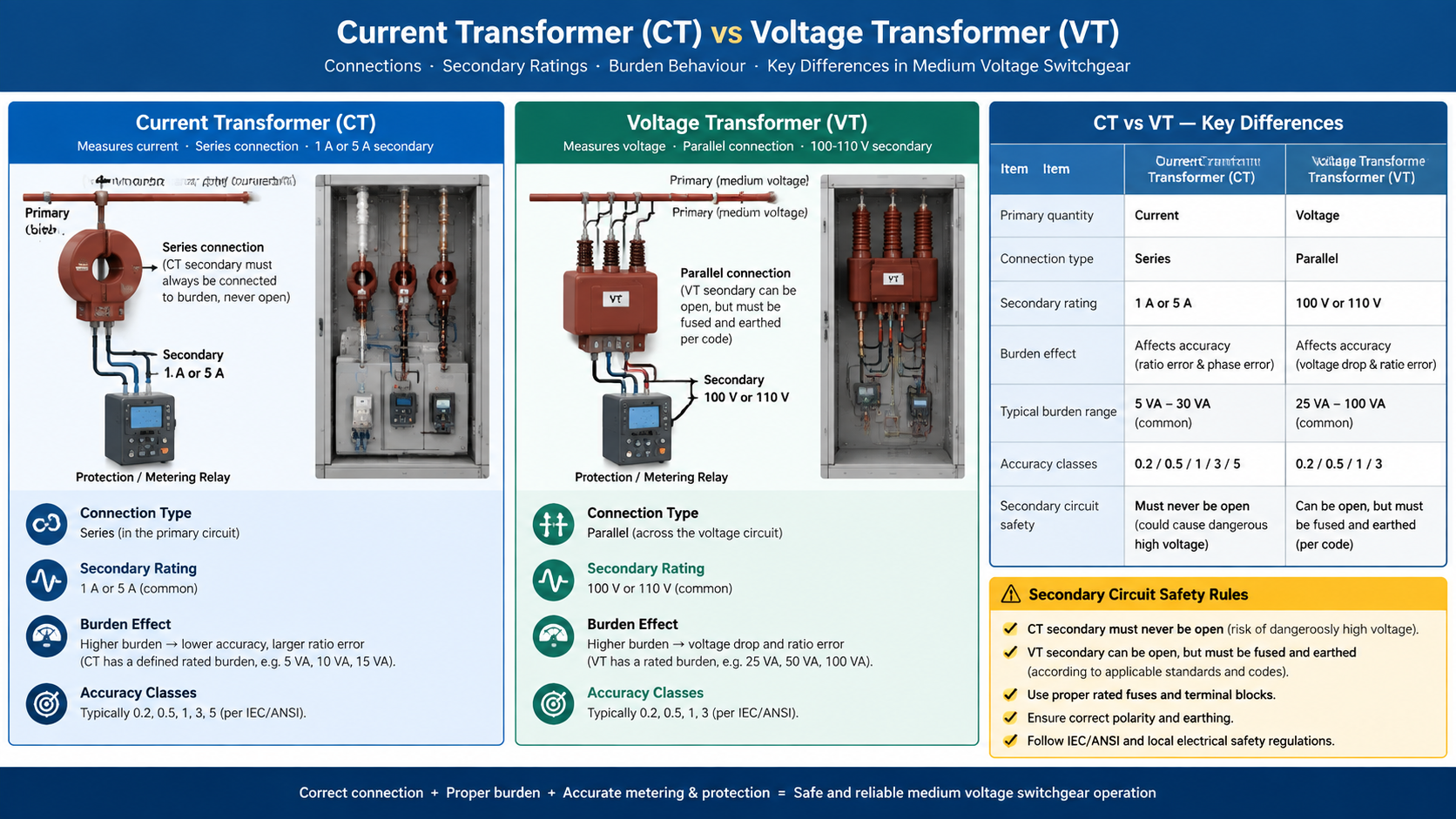
The distinction is not academic. A VT cannot measure current, because its primary is designed to see essentially the full system voltage and almost no current. A CT cannot measure voltage, because its primary sees the full system current and a negligible voltage drop. Attempting to substitute one for the other produces either a reading with no meaning or a failure — and in the case of an accidentally opened CT secondary, an immediate safety hazard. This is why instrument-transformer secondary circuits are built, labelled, and tested as their own protection scheme rather than as a simple metering connection.
The same reasoning explains why the wiring around each device looks so different. CT secondary circuits use dedicated terminal blocks with shorting links and are often earthed at one point only. VT secondary circuits use fuses or miniature circuit breakers on each phase and are earthed at one secondary terminal. In a fully assembled medium and high voltage switchgear bay both types are wired back to the same relay panel, which is why their secondary circuits are commissioned and tested as one scheme.
In practice, most MV panels need both, plus a third type for mixed duties.
For a cast-resin indoor switchgear application, a device such as the LZZBJ9-10 current transformer covers the metering and protection duties of a 10 kV panel in one unit, with selectable ratios and accuracy classes for each core. The equivalent VT function is normally provided by a separate voltage transformer or a combined unit.
Where space is tight, a combined instrument transformer houses a CT and a VT in one housing, reducing the number of units, support structures, and connections in a bay — a common arrangement in compact substations and retrofit projects. Gas-insulated designs serve the same purpose in GIS switchgear. Rogowski coils and current clamps take a different route entirely: because their output is a voltage proportional to the rate of change of current, they have no iron core to saturate and are useful for wideband or transient measurement, though they need an integrator to produce a usable signal.
The CT versus VT distinction comes down to what each device replaces on the instrument side: a large current or a large voltage. A CT is a series device with a fixed secondary current, a VT is a parallel device with a fixed secondary voltage, and the safety rules that surround each follow directly from those two facts. Specify them together, check the burden of the whole secondary circuit, and the metering and protection scheme will behave the way the single-line diagram promises.
Instrument transformers are only one part of the assembly. Our guide to high voltage switchgear shows how CTs, VTs, breakers, and disconnectors are arranged inside a complete panel, and if you need help matching ratios and classes to your protection scheme, send us your single-line diagram and relay settings.
A current transformer measures current and is connected in series with the conductor, producing a standard secondary output of 1 A or 5 A. A voltage transformer measures voltage, is connected in parallel, and produces a standard secondary output of about 100 V or 110 V.
With the primary energised and the secondary open, there is no burden to limit the voltage, so the secondary can develop a very high potential that endangers people and insulation and can permanently damage the core.
Yes. A VT secondary carries almost no current, so leaving it open is harmless. Its accuracy does depend on burden, so excessive loading shifts the reading rather than damaging the transformer.
It is a single unit containing both a current transformer and a voltage transformer, used to reduce the number of devices, supports, and connections in a switchgear bay.
Revenue and sub-metering normally use class 0.2S, 0.5, or 1. Protection uses classes such as 5P or 10P, because protection cores must remain dependable and accurate during fault currents rather than at normal load.
They need protection of the secondary circuit rather than the transformer itself: shorting links and dedicated terminal blocks for CTs, and fuses or miniature circuit breakers for VTs, with a single earth point on each circuit.