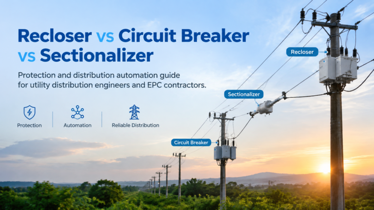
Recloser vs Circuit Breaker vs Sectionalizer
The functional differences between a recloser, a circuit breaker and a sectionalizer, how the three coordinate to isolate a faulted section, and which arrangement suits each network.
Read More
Most current transformer problems are not manufacturing defects. They are selection errors — a ratio that saturates on faults, an accuracy class that drifts at low load, or a burden that was never recalculated after two more meters were added to the panel.
This guide walks through How to Select a Current Transformer in the order a specifying engineer actually has to make the decisions: define the duty, calculate the ratio, choose the accuracy class and burden, verify the protection performance, and then match the construction to the installation. It applies to cast-resin indoor units and to outdoor, oil-immersed, and bar-primary designs alike, because the electrical logic does not change with the housing.
Every current transformer has to serve one or more of three duties, and each duty has different accuracy requirements:
Where metering and protection duties share one physical device, the correct answer is a multi-core CT with a metering core and a protection core on the same primary, rather than one compromise core. Where voltage measurement is also needed in the same bay, it is handled by a separate voltage transformer such as the JDZ10-10 voltage transformer. The LZZBJ9-10 current transformer is a typical indoor cast-resin example, with selectable ratios and separate cores for metering and protection duty in a 10 kV panel.
The ratio is written as primary/secondary, for example 600/5 A. Select it from three inputs, in this order.
Start with the maximum expected continuous current on the circuit, then add margin for future load and for derating at higher ambient temperature. A common rule is to select the next standard ratio above the calculated continuous current, so the CT operates at 60–80% of rated primary current at normal load rather than at its limit.
The primary rating must also be sensible relative to the prospective fault current, because the ratio and the accuracy limit factor together determine whether the core saturates before the relay sees the fault. Ratios chosen only from load current are the most frequent cause of protection under-reach.
| Secondary rating | Advantages | Best suited to |
|---|---|---|
| 1 A | Lower burden on long secondary runs, lower VA requirement, smaller cable cross-section | Substations and switchrooms with long cable runs between CT and relay panel |
| 5 A | Higher secondary voltage available for a given burden, widely available instruments, better immunity to noise on short runs | Compact installations with short, local secondary wiring |
Standard secondary current is 1 A or 5 A. Pick the value that matches the existing panel and relay family, then size the cable accordingly.
Accuracy class defines the permitted error at rated current, and the burden defines how much connected load the CT can carry while still meeting that class. They must be read together: a class 0.5 CT at half its rated burden is not the same device as a class 0.5 CT operating at its accuracy limit.
| Class | Duty | What it guarantees |
|---|---|---|
| 0.2S / 0.2 | Revenue metering | Tight error limits, with the “S” classes holding accuracy down to very low primary current |
| 0.5 | Sub-metering, power measurement | Balanced accuracy and cost for commercial and industrial metering |
| 1.0 | Ammeters, monitoring | Indication-grade accuracy |
| 5P | Protection | Composite error limited to 5% at the accuracy limit factor; common for overcurrent and earth fault |
| 10P | Protection | Composite error limited to 10%; used where larger errors are tolerable |
Burden is expressed in VA at a stated power factor, conventionally 0.8 inductive. Add up the VA of every connected device, add the cable burden calculated from the secondary current and the round-trip cable resistance, add a margin for future additions, and select a CT whose rated burden exceeds the total. Under-burdening a CT is safe; over-burdening it silently degrades accuracy and protection performance.
For protection cores, the accuracy limit factor (ALF) states how many times rated primary current the core can carry while staying within its composite error. A 5P10 CT is therefore a 5P core with an ALF of 10.
To check whether that is enough, compare the maximum fault current in primary terms with the rated primary current, then allow for the relay or device connected. If the calculated multiple exceeds the ALF, the core saturates during the fault and the relay sees less current than the network is actually delivering. The practical fixes are a higher ALF, a lower ratio with a higher ALF, or a different core arrangement — not a change to the relay settings.
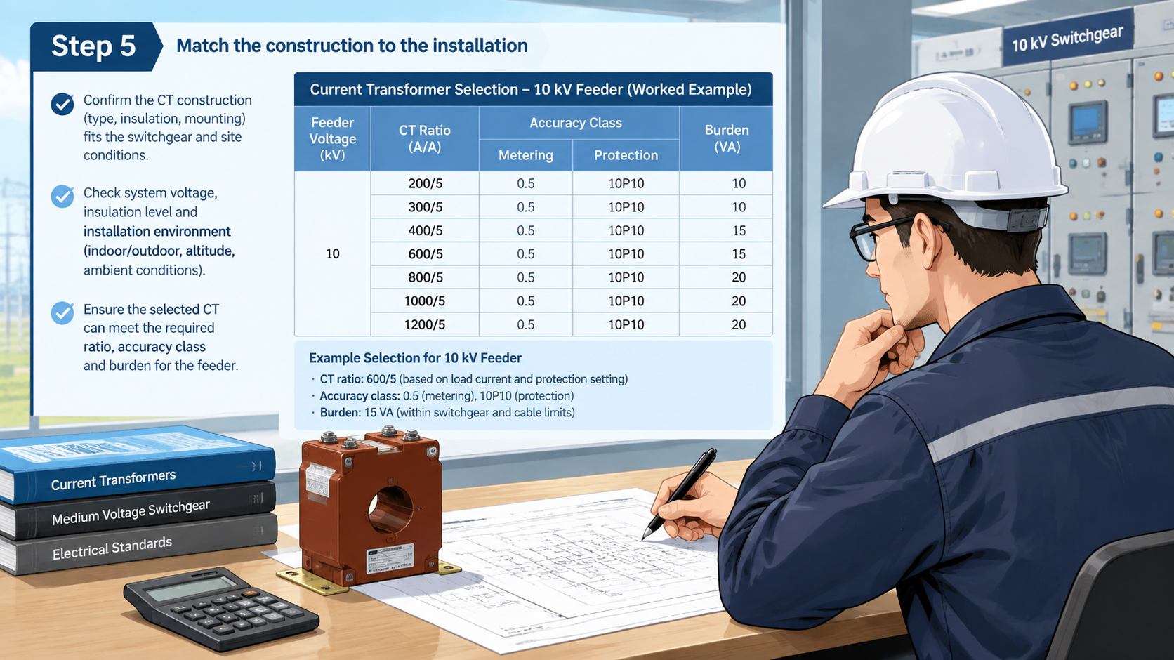
Whatever the construction, the CT has to fit the geometry of the panel it lives in. The medium and high voltage switchgear range shows the mounting arrangements these cores are designed for, and the panel-level view in our high voltage switchgear guide explains how the CT, breaker, and disconnector positions relate to one another.
Whatever the construction, confirm the short-time thermal current and dynamic current ratings against the system’s fault level. Those ratings protect the CT itself and the panel around it, and they are specified separately from accuracy.
| Input | Value | Selection decision |
|---|---|---|
| Circuit | 10 kV feeder, 400 A normal load | Indoor cast-resin CT, switchgear mounting |
| Prospective fault current | 20 kA | Compare with short-time thermal and dynamic ratings |
| Continuous current with margin | ≈ 480 A | Select 600/5 A primary ratio |
| Duties required | Metering plus overcurrent protection | Dual-core CT: class 0.5 metering core and 5P10 protection core |
| Connected burden | Meter 3 VA, relay 1 VA, cable 2 VA, future margin 2 VA | Select 15 VA rated burden at class 0.5 |
| Fault multiple | 20 kA / 600 A ≈ 33 times rated | Confirm ALF with a coordination check; a switchgear CT with a higher ALF may be required |
Reliable current transformer selection follows a fixed order: define whether the core is for metering or protection, size the ratio from both continuous load and fault current, choose the accuracy class and burden as a pair, verify the accuracy limit factor against the real fault multiple, and only then pick the construction and housing that fit the switchgear. Get those five steps right and the CT will remain accurate for its whole service life; skip any one of them and the error usually surfaces later as a metering dispute or a relay that fails to operate.
The CT is one item in a larger assembly. Our overview of the medium voltage circuit breaker explains how protection devices coordinate inside a feeder panel, and we are glad to review your ratios and classes against the single-line diagram before you place an order.
Start from the maximum continuous current plus a margin for future load, select the next standard ratio above it, and then check the ratio again against the prospective fault current to confirm that the protection core will not saturate during a fault.
Class 0.5 suits most commercial and industrial sub-metering. Revenue metering at low load benefits from class 0.2S or 0.5S, because the “S” classes maintain accuracy down to a small percentage of rated current.
It describes a protection core with a composite error limited to 5% up to ten times rated primary current — in other words, accuracy class 5P with an accuracy limit factor of 10.
Use 1 A for long secondary cable runs, because it reduces burden and cable cross-section. Use 5 A for short local wiring where standard instruments and relays are already rated for it.
The CT only meets its stated accuracy class up to its rated burden. Exceeding that burden increases errors and can degrade protection performance, so recalculate the total VA whenever devices or cable lengths change.
Often yes. Sensitive earth-fault protection may require a dedicated core or a core-balance type CT, because the residual current signal is small and phase cores optimised for overcurrent duty may not resolve it accurately.