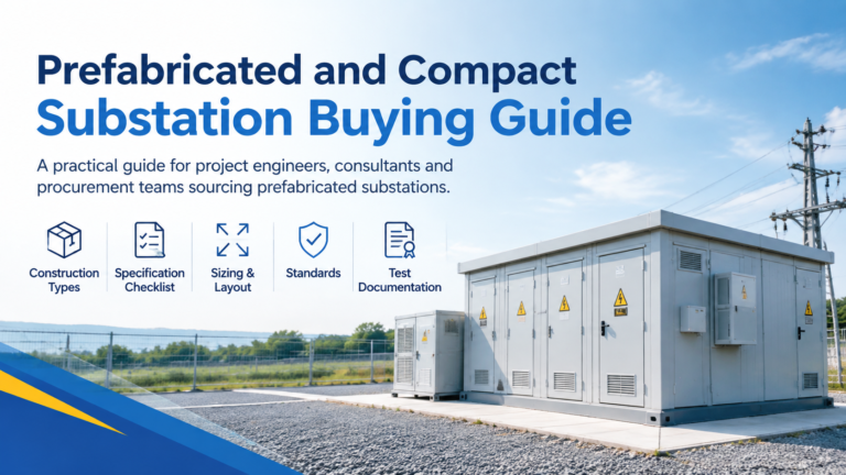
Prefabricated / Compact Substation Buying Guide
A compact substation buying guide covering construction types, when a prefabricated unit beats a switchroom, the specification checklist, sizing, layout and required test documentation.
Read More
An EV charging hub is a small distribution substation with a retail interface. The chargers get the attention, but the EV charging stations switchgear and the equipment behind it decide how much power the site can actually deliver, how quickly it can be commissioned, and whether the utility demand charge erases the margin on every session.
This guide follows the electrical path from the medium-voltage feeder to the charger terminals, shows how to size the station from charger count and simultaneity rather than nameplate totals, and sets out the protection, earthing and enclosure requirements that differ from ordinary commercial distribution. The range of distribution solutions for charging and similar public-facing infrastructure follows the same principles.
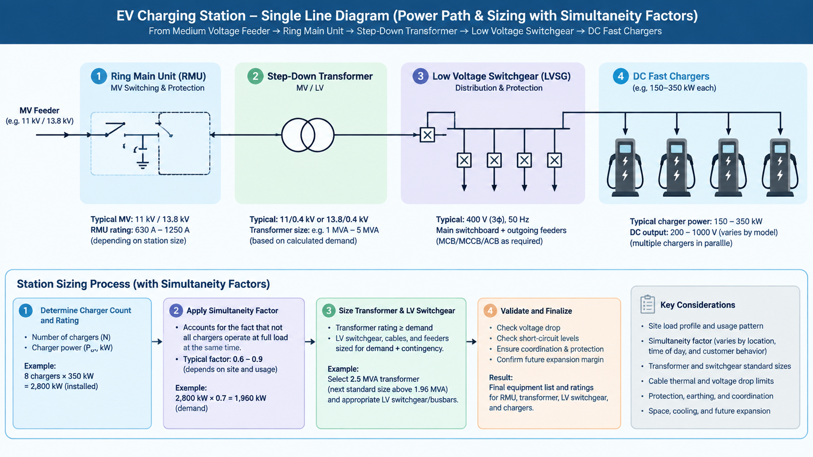
The design load is not the sum of charger nameplates. It is the sum multiplied by a simultaneity factor and divided by efficiency and power factor, plus the auxiliary load, plus a margin.
Design apparent power ≈ (number of chargers × charger power × simultaneity factor) ÷ (charger efficiency × power factor) + auxiliary load, then apply a margin of at least 20% for expansion, harmonic derating and ambient temperature before rounding up to the nearest standard transformer rating.
| Number of chargers | Typical simultaneity factor | Practical effect |
|---|---|---|
| 2–5 | 0.75–0.90 | Sites with little or no load management |
| 6–10 | 0.60–0.75 | Managed sites where sessions rarely overlap fully |
| 11–20 | 0.50–0.65 | Highway and urban hubs with power sharing |
| 20+ | 0.45–0.55 | Mega hubs with active power allocation across stalls |
Because the transformer is the most expensive and least upgradable item on site, the sizing calculation deserves more attention than the charger selection. A station with intelligent power sharing can often run on a transformer one or two standard steps smaller than an unmanaged site, which changes both capital cost and the utility demand charge.
| Characteristic | Ring main unit | Circuit breaker panel |
|---|---|---|
| Primary switching | Load break switches, with fuses on the transformer feeder | Vacuum circuit breakers |
| Fault clearance | By MV fuses | By breaker and protection relay with adjustable settings |
| Protection features | Basic, determined by fuse characteristics | Overcurrent, earth fault and reclosing functions |
| Footprint and cost | Compact and typically substantially cheaper | Larger and more expensive |
| Best suited to | Stations with a single transformer and radial feeders | Large hubs with multiple transformers or a ring network |
For most sites with a handful of chargers and one transformer, a ring main unit with a fused transformer feeder is the standard answer, and it integrates neatly into a compact substation enclosure. Where the connection point has a high fault level, where several transformers must be coordinated, or where the utility requires adjustable protection settings, a breaker-based panel is the correct choice — the same reasoning that governs the medium and high voltage switchgear used in any distribution project. Insulation technology is a separate decision again, and the trade-offs are set out in our comparison of AIS and GIS switchgear.
The LV side is where most site-specific requirements concentrate.
Charging sites are frequently constrained by land, planning conditions and programme. Integrating the MV switchgear, transformer and LV distribution into a single factory-assembled, weatherproof enclosure removes most of the on-site electrical construction, shortens the critical path and makes the installation removable if the site lease ends. A compact ring main unit feeding the transformer, paired with LV assemblies and an outdoor distribution enclosure such as the outdoor low voltage distribution cabinet, is a common arrangement; the wider low voltage switchgear range covers the outgoing feeder protection and metering.
Power availability, not real estate, is usually the binding constraint. Before committing to a site, establish the available connection voltage and approved demand, the distance to the point of connection, the prospective fault level, and the utility’s lead time for a new service or upgrade — the last of these can run to many months and will govern the opening date.
Where the grid cannot deliver the required peak economically, a buffered arrangement using battery storage, on-site generation or solar canopies reduces the connection size and the demand charge; all of them add their own interconnection and protection requirements, so they belong in the design from the start rather than being retrofitted.
A charging station is designed from the load backwards: establish the real simultaneous demand, size the transformer with proper margin, choose ring main unit or breaker panel according to fault level and coordination needs, then build the LV side around continuous duty, type B residual current protection and clean earthing. Get that order right and the site will deliver its rated output on day one and accept additional chargers later without a rebuild.
If you are planning a charging hub, send us the charger schedule, simultaneity assumptions and available utility supply, and we will help size the MV and LV distribution and confirm the configuration that fits the site.
Medium-voltage switchgear — usually a ring main unit with a fused transformer feeder for smaller stations, or a circuit breaker panel where fault levels are high or multiple transformers must be coordinated — plus low-voltage switchgear for the incoming supply, charger feeders, power factor correction and surge protection.
No. Apply a simultaneity factor, divide by charger efficiency and power factor, add the auxiliary load, and allow a margin of at least 20%. Managed sites with power sharing can use a significantly smaller transformer than the arithmetic total suggests.
DC fast chargers can produce smooth DC fault currents that type A devices are not designed to detect. Type B residual current devices are required so that a DC earth fault is detected and the circuit is disconnected.
Where the available fault level is high, where several transformers or transformer feeders need coordinated protection with adjustable settings, where a ring network is used, or where the utility requires relay-based protection and remote indication.
By managing the site peak: sequencing sessions through power sharing and charge scheduling, buffering with battery storage, or adding on-site solar. All three reduce the highest monthly peak, which is the value the demand charge is based on.
Yes, and it is often the fastest option. A prefabricated enclosure integrating the MV switchgear, transformer and low-voltage distribution is factory assembled and tested, which reduces civil works and site time considerably.