EV Charging Stations Switchgear Application Solution
How to specify EV charging station switchgear: the power path from MV feeder to charger, load sizing with simultaneity, MV switch options, LV protection and compact substations.
Read More
A renewable plant either reaches the grid reliably or spends its life chasing faults, and the difference is usually in the collector network rather than in the panels or turbines. Wind/Solar Farm MV Switchgear have to do something conventional distribution equipment is not designed for: switch a variable, intermittent source many times a day, in a remote and often hostile environment, and remain certifiable for project finance.
This guide sets out what the collector network has to achieve, how solar and wind duties differ, the ratings and derating that follow from intermittent generation, and the enclosure and grid code requirements that decide whether the equipment survives twenty-five years on site. The broader power distribution solutions offered for generation and grid connection projects follow the same logic.
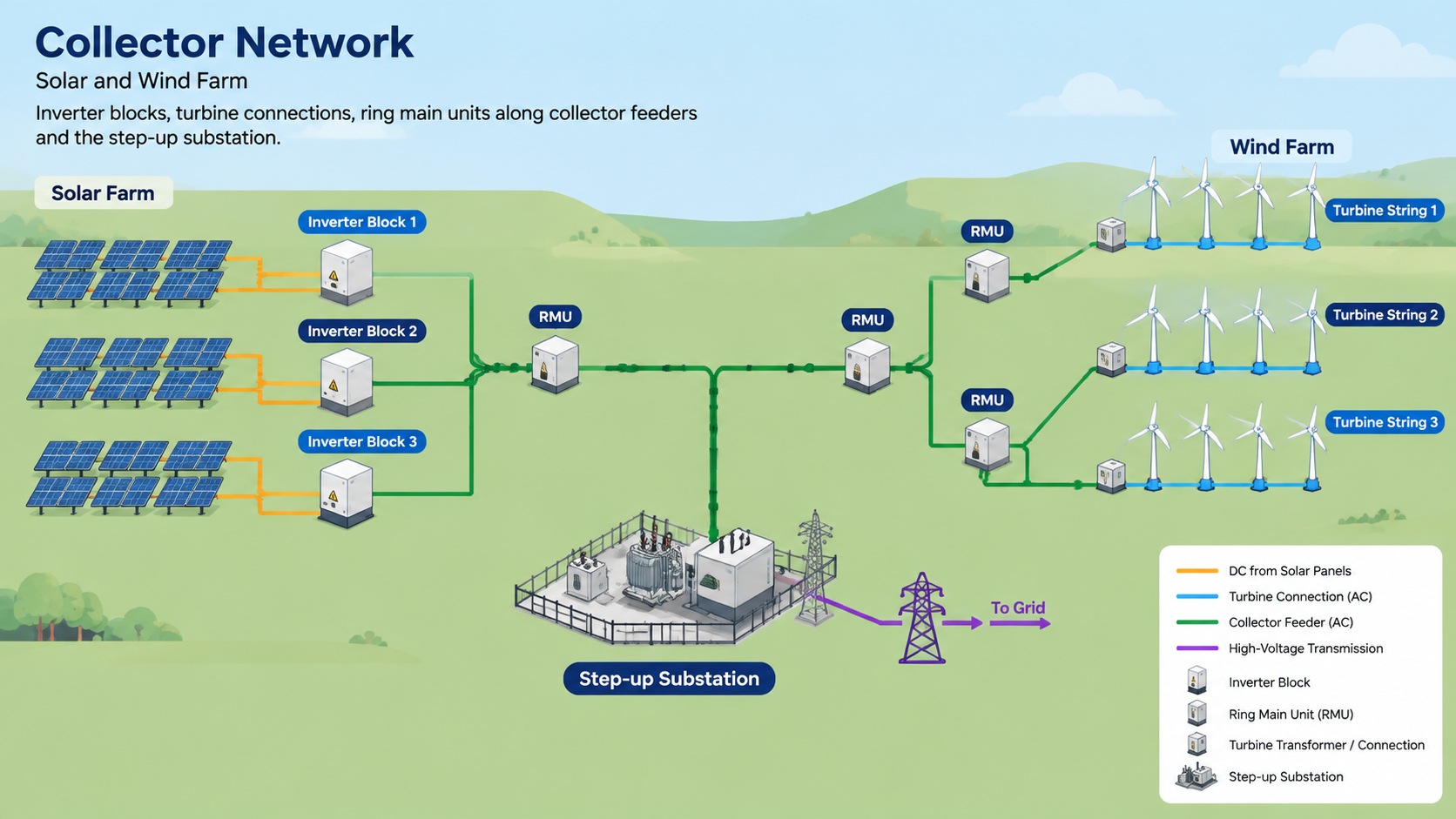
In a utility-scale solar plant the electrical path is straightforward in principle: panels produce direct current, inverters convert it to alternating current, the collector network gathers the inverter output, and a step-up substation raises it to the grid connection voltage. Wind is the same idea with a different shape — each turbine has its own transformer at the tower base or in the nacelle, and a collector cable system gathers the output before it reaches the plant substation.
Switchgear sits at three positions in that chain, and each has a different job:
| Factor | Solar PV | Wind |
|---|---|---|
| Layout | Wide network with many distributed inverters | Turbine-based layout with long collector cable runs |
| Output variability | Smooth changes, midday peak, cloud-driven cycling | Fast and irregular fluctuation with gust-driven torque variation |
| Switching operations | High — daily start and stop plus cloud cover cycling | High — start and stop cycles plus fault ride-through events |
| Site conditions | Heat, dust, sand, high solar exposure | Cold, moisture, salt, vibration, offshore or remote access |
| Footprint | Modular layouts with room to build | Tight footprint at the tower base or inside the nacelle |
| Maintenance access | Ground level and relatively easy | Difficult, expensive, sometimes weather-limited |
The practical consequences are worth stating plainly. Solar favours modular, easily expandable lineups with ground-level access. Wind favours compact, sealed, vibration-tolerant equipment that needs the fewest possible site visits, and offshore wind pushes that preference to the extreme.
Renewable generation does not present a steady load, so ratings are set with margin above the source’s maximum output rather than at it.
| Parameter | Solar | Wind |
|---|---|---|
| Continuous current rating | About 1.25 times peak inverter output | About 1.3 times maximum turbine output |
| Short-circuit withstand | Commonly 25–31.5 kA | Commonly 31.5–40 kA |
| Voltage deviation tolerated | Around ±5% | Around ±7% |
Two further effects are easy to miss. First, ambient temperature derating: equipment rated at a temperate ambient loses capacity in a desert or a hot plant room, and the enclosure design has to compensate. Second, altitude: dielectric and thermal performance both fall with height, so equipment for high-altitude sites must be selected with a reduction factor rather than at nameplate. Both are specified before the equipment is ordered, because neither can be fixed on site.
Air-insulated switchgear remains the default for the common collector voltages because it is modular, easy to service and inexpensive. Two alternatives dominate where the environment or the footprint rules it out:
Where the substation has sufficient space and a clean environment, the simpler air-insulated arrangement usually wins on serviceability. Where it does not, the sealed alternatives pay for themselves in avoided maintenance visits. Our comparison of AIS and GIS switchgear works through the trade-offs in detail.
Solar and wind assets switch far more often than a conventional distribution feeder. A photovoltaic plant may start and stop daily and cycle repeatedly as cloud passes; a wind turbine starts and stops with the wind. Oil and air-break switchgear wears quickly under that duty, while vacuum interruption is designed for a very large number of operations with minimal contact wear and no medium to replenish.
That is why vacuum interrupters inside metal-enclosed or sealed assemblies have become the standard choice for renewable collectors, and why the vacuum circuit breaker is the reference device for the higher-duty positions in the network. Maintenance planning for those breakers follows the same principles as any other MV installation.
Renewable sites are chosen for resource, not for climate. The enclosure specification has to be set from the actual micro-climate of the site rather than a generic outdoor rating:
Outdoor insulation is part of the same environmental package. Bushings, cable terminations and line insulators have to be specified for the pollution class of the site rather than treated as standard fittings, and a composite insulator is often the practical answer where salt or industrial contamination is severe.
Connecting a generator to the network brings obligations that do not apply to a passive load. The protection and control scheme in the collector switchgear must be capable of implementing the grid code requirements at that connection point — typically fault ride-through behaviour, reactive power control, voltage and frequency tolerance, and power quality limits. Modern practice is to use numerical relays and communications that integrate with the plant SCADA system so the operator and the grid operator both see the same data.
Certification carries unusual weight on these projects. Because lenders, insurers and grid operators all rely on documented performance, the switchgear should carry type tests from an independent laboratory to the relevant standard, along with the utility’s own approval where required. Routine test certificates, drawings and protection settings are part of the deliverable, not an afterthought.
Compact ring main units are the usual building block for collector networks, connecting adjacent inverter blocks or turbines in a loop so that a single cable fault can be isolated without losing the whole string. Where the collector meets the step-up transformer and the grid connection, full circuit breaker lineups take over, because that is where fault levels and coordination requirements are highest. A compact sealed assembly such as the XGN15-12F ring main unit covers the collector duty, and the wider medium and high voltage switchgear range covers the substation end of the same scheme.
Renewable collector switchgear is specified around three realities: high switching duty, intermittent generation and a hostile environment. Rate the equipment above the source’s maximum output with proper derating, choose vacuum interruption for the switching duty, set the enclosure from the site micro-climate rather than a generic rating, and provide protection and control that can demonstrate grid code compliance to a lender and a grid operator. Do that and the switchgear becomes the least eventful part of the plant, which is exactly the objective.
Send us the collector network single-line diagram, the inverter or turbine ratings, the site conditions and the grid connection requirements, and we will advise on the switchgear configuration and insulation technology for your project.
Most collector networks operate in the medium-voltage range up to about 36 kV, with 33 kV and 35 kV common for utility-scale solar and 12–15 kV used on smaller wind projects. Higher connection voltages appear at the plant substation where the collector feeds a step-up transformer.
Because the switching duty is high. Solar plants cycle with cloud cover and daily start-stop, and turbines start and stop with the wind, so equipment must tolerate a very large number of operations. Vacuum interruption wears little under that duty and needs no arc-quenching medium.
A ring main unit is a specific, compact form of switchgear used to build looped networks — connecting adjacent turbines or inverter blocks while maintaining the ring topology. The plant substation uses larger circuit breaker lineups where fault levels and coordination requirements are higher.
A common starting point is around 1.25 times peak inverter output for solar and about 1.3 times maximum turbine output for wind, before applying derating for ambient temperature and altitude and checking the short-circuit withstand against the actual fault level.
It can, but only inside a shelter providing equivalent environmental protection, ventilation and safe access. Outdoor-rated equipment is usually simpler and more reliable than building around an indoor design.
Type test certificates from an independent laboratory, routine test certificates for the delivered units, protection settings and coordination study, arrangement and schematic drawings, and the grid operator’s approval where required.