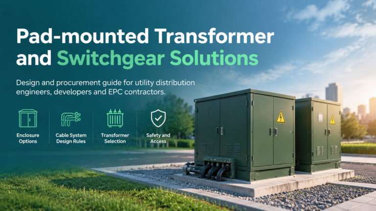
Pad-mounted Transformer & Switchgear Solutions
Pad-mounted distribution design: the switchgear options, underground cable design rules, transformer selection for a pad-mounted enclosure, safety and access, and a procurement checklist.
Read More
Data Centers MV Switchgear power distribution is designed backwards from the load: uptime tier first, redundancy second, equipment last. That order is what makes data center switchgear different from equivalent equipment in a factory or a commercial building. A medium-voltage lineup in a data centre has to support concurrent maintenance without dropping critical load, contain an internal arc rather than vent it toward people, and report its condition into a monitoring platform.
This guide covers the distribution architectures used in modern facilities, the ratings and construction features that MV switchgear needs, and the practical details — control power, physical separation, protection coordination — that decide whether a design that looks redundant on paper actually behaves that way. The wider range of power distribution solutions for critical facilities follows the same engineering logic.
These four constraints push the design toward a small number of well-understood topologies and a strict separation discipline, rather than toward unusual equipment.
| Topology | How it is arranged | What it delivers |
|---|---|---|
| Radial | One MV source per transformer and downstream line | Lowest cost; no MV redundancy, so IT-level dual cord protection has to compensate |
| Main-tie-main | Two incomings with a normally open tie breaker between bus sections | Concurrently maintainable sources; the surviving source must carry the full load |
| Double-ended with dual tie | Two incomings, sectionalised bus, two ties | A bus section can be taken out while source redundancy is retained on the rest |
| Ring or loop bus | Feeders served from a loop with sectionalising switchgear | Isolates a cable fault without losing a whole building; suits campus MV distribution |
| 2N | Two fully independent MV systems and transformer sets, no shared component | Fault tolerance: an MV bus fault on one path does not touch the other |
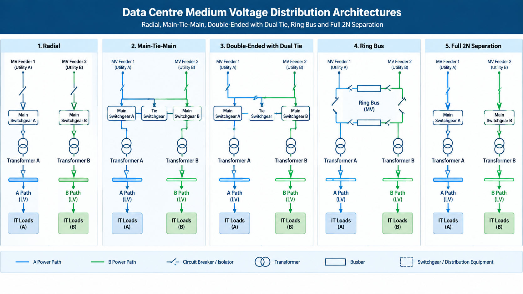
The choice is driven by the availability objective. Main-tie-main is the common answer for concurrently maintainable facilities because it provides two serviceable paths without duplicating everything. Fault tolerance is a stricter test, and it is the reason tier IV designs carry the A/B separation all the way up to the medium-voltage level rather than stopping at the UPS.
The values below are typical rather than prescriptive, because the fault level and the final load come from the network study rather than from the building floor area. The device that sits inside this construction is described separately in our guide to the medium voltage circuit breaker.
| Parameter | Typical data centre value | Why it matters |
|---|---|---|
| Rated voltage | 12 kV or 36 kV class | Selected for the distribution voltage with margin for transients |
| Bus current | 2,500–4,000 A | Sized for final facility load plus growth margin |
| Short-circuit withstand | 25–50 kA for 3 s | Must exceed the prospective fault level at the point of connection |
| Internal arc classification | Arc-tested with directed exhaust away from access routes | Protects personnel; the vent direction has to suit the room layout |
| Construction | Metal-clad with compartmentalised breaker, bus and cable zones, drawout breakers, insulated bus, automatic shutters | Supports maintenance without a full shutdown and contains an internal fault |
| Protection and control | Numerical relays with overcurrent, earth fault, differential and bus zone functions | Selective coordination is a code requirement in critical operations areas, not a preference |
| Monitoring | Integrated metering and communications back to the DCIM platform | Real-time current, voltage, power factor and thermal reporting |
On the insulation side, air-insulated switchgear remains the default in the 5–15 kV class, while compact gas-insulated or sealed designs become attractive at 34.5 kV and above, in space-constrained urban facilities, or where humidity and dust would otherwise dictate heavy maintenance. Where the design moves to gas insulation, the SF6 inventory becomes a reporting item, which is why sealed and SF6-free alternatives now feature in new campus specifications. The trade-offs between the two construction families are set out in our comparison of AIS and GIS switchgear.
A 2N single-line diagram is necessary but not sufficient. Many facilities that are 2N on paper are N in practice, because the redundancy stops at the primary equipment. Check these alongside the main scheme:
The audit rule is simple: apply the same rigour to the auxiliary systems as to the primary ones, and confirm that no two “independent” paths converge on shared upstream equipment at any point.
Overcurrent protection alone is not enough at this fault level. A bus zone differential scheme detects a fault inside the switchgear lineup and trips it in a few milliseconds, which is what limits the damage an internal arc can do. Where feeders are also expected to reclose automatically, the same coordination has to be extended to the reclose logic — the roles of the three devices are compared in our guide to the recloser, circuit breaker and sectionalizer. Protection coordination has to be demonstrated by study rather than assumed: a rack-level fault must clear at the nearest upstream device without disturbing the main bus, and transfer logic must be coordinated with generator start sequences where the surviving source is generator-backed.
Metering covers two duties that are often confused. Revenue metering sits at the point of connection, while operational metering lives in the relays and the switchgear monitoring package and feeds the DCIM platform. Both should be commissioned to the same accuracy expectations, and thermal monitoring on busbar joints and cable terminations gives the earliest warning of a developing connection problem.
In urban and basement plant rooms, the electrical footprint is often the binding constraint, and civil works on a critical-path project are expensive. Two techniques are standard: using compact sealed switchgear, and moving plant into factory-built assemblies. A ring main unit or a compact ring main unit configuration is well suited to ring and transformer circuits where a full lineup would be oversized, and prefabricated assemblies shift cable termination, protection testing and interlocking checks into the factory, where they can be repeated under controlled conditions before delivery.
Commissioning should be planned as part of that logic. Factory acceptance testing of the assemblies, documented type and routine tests, and a clear interface between the switchgear scope and the downstream LV and UPS scope together eliminate most of the surprises that appear during energisation.
Data centre MV distribution is a discipline of separation and demonstrable performance. Fix the availability objective first, then choose the topology, then specify switchgear by voltage, current, fault level, arc class and construction — and finish by auditing the auxiliary systems that quietly decide whether the redundancy is real. Equipment is the last decision, not the first, because the best lineup in the world cannot fix a single point of failure in the control power.
If you are specifying MV distribution for a data centre or a critical facility, send us the single-line diagram, fault level and target tier, and we will advise on the switchgear configuration and alignment with the medium and high voltage switchgear range that fits the available footprint.
Most facilities distribute at 12 kV or 36 kV class, with the exact value set by the utility supply and the step-down transformer primary. Higher classes such as 34.5 kV appear where the utility connection voltage demands it or where a large campus benefits from distributing at a higher voltage.
Main-tie-main uses two incomings and a normally open tie so either source can carry the whole load, giving concurrently maintainable paths. 2N duplicates every element in two fully independent systems with no shared component, which is what fault tolerance requires.
It ensures a fault at a downstream circuit clears at the nearest upstream protective device instead of tripping the main bus. Without it, a local fault becomes a facility-wide outage, so coordination is verified by study rather than assumed from ratings.
Not always. AIS is the default in the 5–15 kV class. GIS or sealed designs become preferable at higher voltages, in space-constrained sites, or where dust and humidity would otherwise force frequent maintenance — provided the operator is comfortable with the gas inventory and reporting obligations.
Shared auxiliary systems: a single station battery, a common automation controller, A and B feeders in the same duct bank, or redundant lineups without fire-rated separation. These convert a 2N design into an N design without appearing on the main single-line diagram.
By using compact sealed switchgear, applying ring main units on ring and transformer circuits instead of full lineups, and moving assemblies into factory-built prefabricated units that also shorten the on-site programme.