Blog
General Electric Dryer Fuse Guide Location and Replacement
Complete guide to General Electric dryer fuse location testing replacement tips and genuine part numbers for GE electric dryers
Read More
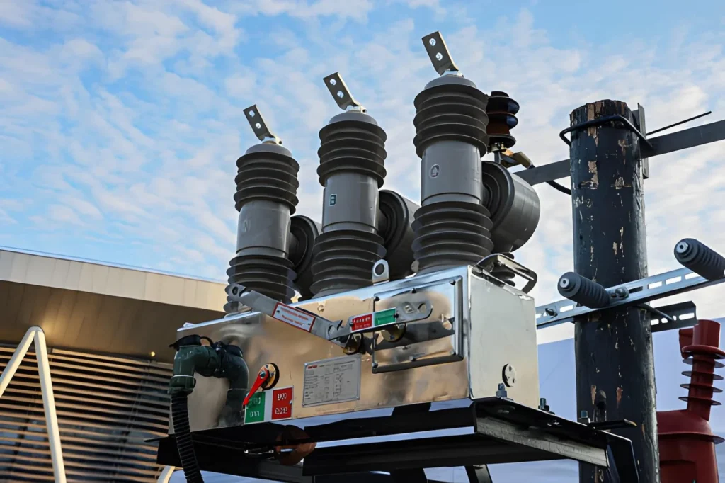
A vacuum circuit breaker (VCB) is a medium-voltage switching device that extinguishes the arc inside a sealed vacuum interrupter rather than in oil, air, or SF₆ gas. When the contacts separate inside the vacuum bottle, the arc is quenched at the first current zero crossing because there are no gas molecules to sustain it. This simple physical difference gives VCBs a long electrical life (typically 10,000 to 30,000 operations at rated current), low maintenance, and an environmentally clean profile — there is no oil to leak, no SF₆ greenhouse gas, and no fire hazard.
Because VCBs are the dominant choice for vacuum circuit breakers in the 3.6 kV to 40.5 kV range — covering industrial plants, utility distribution, mining, data centers, and renewable-energy installations — picking the right one is a decision that affects safety, uptime, and total cost of ownership for the next 20 to 30 years. Choose undersized and you risk nuisance trips, contact erosion, or catastrophic failure to interrupt a fault. Choose oversized and you overspend on the breaker, the switchgear panel, and the busbar system. This selection guide walks you through the ratings, the steps, and the trade-offs so you can specify a VCB with confidence.
Compared with air, oil, or SF₆ breakers, a VCB has three practical advantages that drive most selection decisions:
The trade-off is that VCBs are economically optimized for medium voltage, up to about 40.5 kV standard and 72.5 kV for specialized designs. Above that, SF₆ or other gas-insulated switchgear is still more common — a comparison worth understanding before you finalize the voltage class.
The three failure modes that drive most VCB problems in the field are all selection errors, not manufacturing defects:
Selecting a VCB is therefore a process of matching electrical ratings, mechanical fit, and environmental conditions — not a single number on a nameplate.
Every nameplate and every specification sheet is built from the same seven ratings. Before you compare models, make sure you can read each one and know what it protects.
| Rating | Symbol | What it tells you | Typical values (12 kV class) |
|---|---|---|---|
| Rated maximum voltage | Ur | Highest system voltage the breaker can handle continuously | 7.2 / 12 / 17.5 / 24 / 40.5 kV |
| Rated normal current | In | Continuous current without exceeding temperature limits | 630 / 1250 / 1600 / 2000 / 2500 / 3150 / 4000 A |
| Rated short-circuit breaking current | Isc | Maximum fault current the breaker can safely interrupt | 16 / 20 / 25 / 31.5 / 40 kA |
| Rated short-circuit making current | Ima | Peak current the breaker can close onto during a fault (≈ 2.5 × Isc) | 40 / 50 / 63 / 80 / 100 kA peak |
| Rated short-time withstand current | Ik | Fault current the closed breaker carries for 1 s or 3 s without damage | Equal to Isc for 3 s (typical) |
| Power-frequency withstand and lightning impulse withstand (BIL) | Ud / Up | Dielectric strength against switching surges and lightning | 42 kV / 75 kV peak (12 kV class) |
| Mechanical and electrical endurance | — | Number of open/close operations before major service | 10,000–30,000 mechanical; thousands electrical at full fault |
These ratings are defined in IEC 62271-100 (global) and ANSI/IEEE C37.04 / C37.09 (North America). A breaker that meets both is easier to specify on international projects.
The first number to lock down is the rated maximum voltage (Ur). It must be equal to or greater than the highest voltage that will appear at the breaker terminals, including temporary overvoltages from switching or faults.
A common mistake is to match the breaker’s rated voltage to the nominal system voltage. Instead, pick the next standard voltage class up:
At the same time, verify the lightning impulse withstand voltage (BIL). If the switchgear panel is designed for a higher impulse level than the breaker, the BIL must be coordinated — otherwise a lightning strike on the line can flash over the breaker’s open gap. For a broader view of how VCBs sit inside the switchgear lineup, see our guide to high-voltage switchgear.
Rated normal current (In) is the continuous current the breaker can carry without exceeding the temperature-rise limits of its contacts and terminals. The selection rule is simple: pick the next standard rating above your maximum continuous load current, with a 20 to 25 percent safety margin.
For transformer feeders, calculate the full-load current at the primary voltage (not just the kVA nameplate). For motor feeders, add the service factor and any future load growth. For incoming or bus-tie positions, sum the downstream feeder loads with a diversity factor. This margin does two things — it prevents nuisance thermal aging of the contacts, and it gives you headroom if the facility expands.
Standard ratings for medium-voltage VCBs are 630 A, 1250 A, 1600 A, 2000 A, 2500 A, 3150 A, and 4000 A. Some manufacturers have moved away from 630 A as a minimum and now offer 1250 A as the entry level, so check the product range before finalizing your single-line diagram.
This is the most safety-critical rating. The breaker’s Isc must be equal to or greater than the maximum prospective fault current at the installation point. If it is lower, the breaker can fail to interrupt and the vacuum interrupter can rupture.
To get the right number, run a short-circuit study at every point in the network where a VCB will be installed. The study must account for:
Common 12 kV VCB breaking capacities are 20 kA, 25 kA, 31.5 kA, and 40 kA. The peak making current (Ima) is standardized at approximately 2.5 × Isc, so a 31.5 kA breaker has an 80 kA peak making capability. For a deeper look at how VCBs handle fault duty versus other breaker types, read VCB vs SF₆ circuit breaker.
VCBs are built in two mechanical formats, and the choice affects cost, footprint, and maintenance strategy.
For a critical feeder where downtime is expensive — a hospital, a data center, or a continuous-process plant — the withdrawable format usually pays for itself. For a simple distribution substation with redundant feeders, fixed is often sufficient.
The operating mechanism drives the contacts and stores the energy needed to open and close. Two mechanisms dominate:
While you are specifying the mechanism, also confirm the control voltage (24 V DC, 110 V DC, and 220 V AC/DC are common), the close and trip coil ratings, the motor charging voltage, and the auxiliary contact count. These are the items most often missed on a procurement spec, and they cause the most field delays.
Standard VCB ratings are calibrated for altitudes up to 1000 m and ambient temperatures up to 40 °C. Outside that envelope you must either derate the breaker or specify a model designed for the environment.
The two main corrections are:
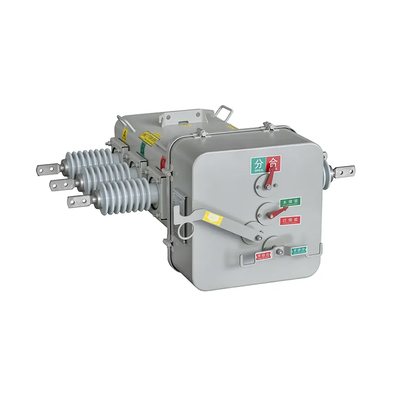
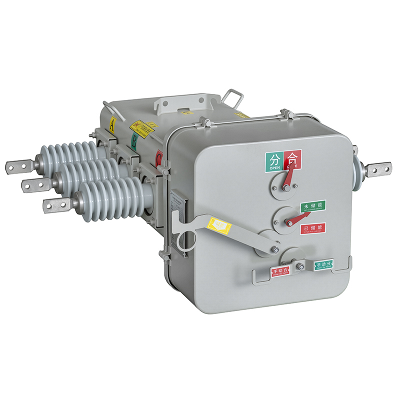
Humidity, dust, salt spray, and chemical vapors push the specification toward a metal-enclosed or embedded-pole design rather than an air-insulated pole. For an outdoor substation, our ZW32-12G T630-20 outdoor AC high-voltage vacuum circuit breaker is a typical example — a sealed, weather-resistant VCB rated for pole-mounted or substation use.
Before issuing a purchase order, confirm the certification and the type test reports. A credible VCB supplier will provide:
Then build the accessories list. The items that get forgotten most often are the shunt trip coil, the under-voltage release, the mechanical interlock, the position auxiliary switch, the door interlock, the earthing switch, and the ratings plate in the local language. Getting the accessories right on the spec sheet avoids expensive retrofit work on site.
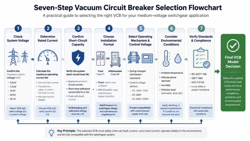
Use this table as a final cross-check before you sign off on a model.
| Item | What to confirm | Done? |
|---|---|---|
| System voltage | Next standard Ur class above nominal | ☐ |
| Continuous current | In ≥ max load × 1.2–1.25 | ☐ |
| Breaking capacity | Isc ≥ calculated prospective fault current (with margin) | ☐ |
| Making capacity | Ima ≈ 2.5 × Isc | ☐ |
| BIL | Matches switchgear rated impulse level | ☐ |
| Installation format | Fixed or withdrawable; panel cutout confirmed | ☐ |
| Mechanism | Spring or magnetic; control voltage confirmed | ☐ |
| Environment | Altitude, temperature, humidity, pollution all addressed | ☐ |
| Standards | IEC 62271-100 / ANSI C37.09 type test reports | ☐ |
| Accessories | Trip coil, UV release, interlocks, aux contacts, nameplate language | ☐ |
Most field problems trace back to one of these five mistakes. Avoiding them is faster and cheaper than fixing them later.
You now have a complete selection framework: the seven ratings, the seven steps, the checklist, the common mistakes, and the FAQ. The fastest way to turn that into a deliverable is to start from the system data you already have — nominal voltage, full-load current, prospective fault current, and the panel cutout — and match them to a VCB model that meets all four with margin.
Browse our full range of indoor and outdoor vacuum circuit breakers, or send us your single-line diagram and we will shortlist models that match your ratings, environment, and budget.
The short-circuit breaking current (Isc) is the most safety-critical rating. If the breaker’s Isc is below the prospective fault current at the installation point, the breaker can fail to interrupt the fault. The rated normal current (In) and the rated voltage (Ur) are the next two numbers to lock in.
Match the breaker to your system voltage, not to the load. An 11 kV system needs a 12 kV class VCB, a 20 kV system needs a 24 kV class VCB, and a 33 kV system needs a 40.5 kV class VCB. If the system is 6.6 kV, specify a 7.2 kV class. For a broader overview of the medium-voltage class, see our medium voltage circuit breaker guide.
Isc is the RMS fault current the breaker can interrupt safely once the contacts are open. Ima is the peak current the breaker can close onto during a fault — the “making” capacity. Ima is standardized at roughly 2.5 × Isc. Both ratings must be greater than the corresponding values at the installation point.
Mechanical life is typically 10,000 to 30,000 open/close operations. Electrical life at full rated fault current is usually a few thousand operations, but at normal load current the vacuum interrupter can last for the full mechanical life without contact service. The vacuum bottle itself is sealed and does not require refilling or reconditioning.
Not without checking the enclosure rating. Indoor VCBs are designed for a clean, temperature-controlled switchgear room. Outdoors, you need a weather-resistant, often metal-enclosed design such as our ZW32-12F outdoor high-voltage vacuum boundary circuit breaker, with appropriate creepage, IP rating, and corrosion protection for the site conditions.
For highly inductive loads (large motors, arc-furnace transformers, shunt reactors) or for cable circuits longer than about 100 m, a surge arrester or RC snubber at the load terminals is recommended. VCBs extinguish the arc very quickly, which can produce current-chopping transients on inductive circuits. For the operating principles behind this, see our guide to vacuum circuit breaker working principle.
Complete guide to General Electric dryer fuse location testing replacement tips and genuine part numbers for GE electric dryers
Read More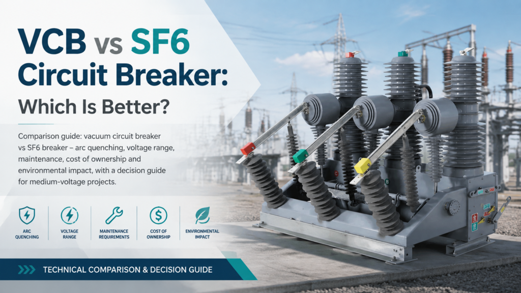
VCB vs SF6 circuit breaker comparison: interrupting medium, voltage range, maintenance, cost of ownership and environmental impact, with a clear decision guide for medium-voltage projects.
Read More
Buyers guide to the best marine electrical fuse block options with waterproof LED panels ABYC compliant features installation tips and top brands
Read More